
Related Manuals for Sun Nuclear 1028

Summary of Contents for Sun Nuclear 1028
- Page 1 1028/1029 Radon Monitor User’s Guide ACCURATE • RELIABLE • ECONOMICAL 1028 1029 RADON Your Partner In Radon Measurement...
- Page 2 Sun Nuclear Corporation reserves the right to make periodic modifications of this product without obligation to notify any person or entity of such revision. The Model 1028 and 1029 Radon Monitors are protected by U.S. Patent #4,871,914 This guide is written for: PC software: version 2.2.0...
-
Page 3: Table Of Contents
Typical Printer Report ... . 23 Sun Nuclear Corporation Symbols . .viii Movement ....24 Operating Information . - Page 4 Specifications ....49 Service and Calibration ... 53 Model 1028/1029 Radon Monitor . . .49 Optional Serial Connection ..53 Connecting with a Serial Cable .
-
Page 5: Preface
Report - Terminology Changes: In the report, the term “Elapsed Time” has been changed to “Exposure Time” per EPA protocols. Also, % has been added to the humidity label on the Model 1029 report page. • Report - Page Numbers: Page numbers are now printed at the bottom of each report page (except the cover page). - Page 6 The chart now displays the overall overage (or EPA overall average) above the legend panel as well as the words ‘Motion Detected’ if a motion event is recorded in the chart. Additionally, if a Model 1029 is connected, the chart will also display the Average Temperature, Average Pressure, and Average Humidity above the legend panel.
-
Page 7: Firmware Changes
• Documents on CD: The CD that is distributed with the Radon Monitor now includes three documents that the inspector can provide to the homeowner. The main screen in the software lists the documents for easy reference. For details, see “Main Screen - Inspection Tab” on page 32. •... -
Page 8: Sun Nuclear Corporation Symbols
Sun Nuclear Corporation Symbols The following symbols are used in this document and in Sun Nuclear Corpora- tion’s product labels. WARNING: Risk of electric shock. WARNING: Possible impact to personal safety. CAUTION: Cautionary statement. Note: Important or supporting information. Manufacturer’s Identification (name and address). -
Page 9: Operating Information
Do not permit water or any other liquids to spill onto the instrument. Inspect Before Use • Inspect all cables periodically for damage. If any mechanical or electrical degradation is suspected, contact Sun Nuclear Corporation for repair or replacement. • Inspect the device periodically for damage. If measurement errors or device damage are suspected, contact Sun Nuclear Corporation. -
Page 10: Online Help
Online Help Online help is available by selecting Help > Contents from the menu bar of the radon monitor software. The Online Help contains the same information included in the radon monitor User’s Guide. About Radon The U.S. Environmental Protection Agency (EPA) maintains a comprehensive web site on radon at: http://www.epa.gov/radon/index.html where you can find PDF and HTML-ready versions of all of EPA's documents, brochures, and publications relating to radon. -
Page 11: Introduction
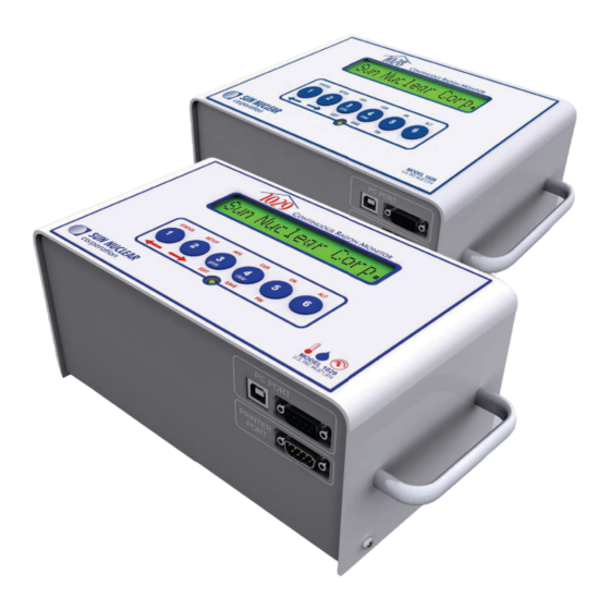
Figure 1. Continuous Radon Monitors, Models 1028 and 1029 This guide covers both the Models 1028 and 1029. Model 1029 has greater sensitivity plus temperature, pressure, and humidity sensors. The radon monitor requires a standard 9V battery. It can be operated on an alkaline battery alone for up to 100 hours or use an AC adaptor and use the battery as a backup power source. -
Page 12: Typical Application
Typical Application In a typical test, place the radon monitor in a building or structure to be monitored, connect power, and leave it unattended for the required test period. Ambient room air, laden with radon, diffuses into the radon monitor’s detection chambers. -
Page 13: Connections
Connections Description Function USB port (USB 1.1 or 2.0); for connection to a USB PC PORT (front) computer Serial PC PORT (front) Serial port (RS-232); for connection to a computer Serial port (RS-232); for connection to the optional PRINTER PORT (front) printer. -
Page 14: Controls
Controls Description Function Display 16-digit LCD display shows messages to guide the operation. Six push buttons have different functions, depending on mode. Press keys to operate. Top row of labels lists main functions. Bottom row of Buttons labels are for Setup. Print and Clear functions are used after measure- ment. -
Page 15: Unpacking
Getting Started Guide (not shown) Figure 4. Parts Furnished with 1028/1029 Radon Monitor *Power converter P/N 700050 is only included with Model 1028/1029 Radon Monitors that are shipped within the United States. International shipments will include the power supply and power cord shown in the table below. -
Page 16: Standalone Operation
Standalone Operation Positioning the Monitor Place the radon monitor in the desired position in the area to be monitored for radon gas. The radon monitor does not need to be level. To use a tripod, thread the standard tripod screw (1/4-20UNC) into the threaded fitting on the bottom of the case (Figure 6). -
Page 17: Ac Adapter
The battery is located in a small compartment on the back of the radon monitor (Figure 7). To install a new battery, see “Changing the 9V Battery” on page 16. A replacement 9V battery can be purchased from Sun Nuclear or any retail source. -
Page 18: Turning On The Display
Figure 8. Connecting Power to the Radon Monitor Plug one end of the power cord into the adaptor and the other end into a 100 to 240 VAC, 50-60 Hz wall outlet. Turning on the Display To conserve power, the 16-digit display is always off until the user presses the ON button. - Page 19 If a Personal Identification Number (PIN) is set up, the display will prompt the user to enter it. Then, the company name is displayed momentarily (if set up) followed by the message “Checking Memory.” If there is data in memory, the message “Data in Memory!”...
-
Page 20: Starting A Test
Starting a Test When the “Start Test = 5” prompt appears, press the 5 button to start a new test (Table 2). Press… Display Shows… Comment – A new test can be started. Start Test = 5 Memory is rechecked. If data is found, memory must be cleared before starting a new test. -
Page 21: Displaying Average And Current
Note: A completed test cannot be interrupted. After a test is com- pleted, pressing ON displays the normal start sequence. See “Turning on the Display” on page 8. Displaying Average and Current AVG or CUR During a Test The average (AVG) or current (CUR) radon values can be displayed during a test. Turn ON the display (see “Interrupting a Test”... -
Page 22: Avg Or Cur After Test
AVG or CUR After Test The average (AVG) and current (CUR) radon values can also be displayed after a test is completed. Turn ON the display (see “Turning on the Display” on page 8), and note the button press options in the table below. Press…... -
Page 23: Checking Unit Status
TIME nn:nn PM – Current date DATE MM DD YY – Date of last calibration. MM/DD/YYYY – Model number (1028 or 1029). SNC MODEL 1028 – Embedded code (firmware) version number. CODE VER nnnn – Serial number. nnnnnnnnnnn End of the menu. Display returns to “Start Test = –... - Page 24 Press SAVE; saves the Delay setting and Interval 1.0 hr advances to Interval. Press arrow keys to scroll through selection of intervals, 0.5 (model 1029 only), 1.0, 2.0, 4.0, 8.0, Interval 4.0 hr 12,16, 20, or 24 hours. Press SAVE; saves the setting and advances to Duration 1.0 hr...
-
Page 25: Character Set
Press… Display Shows… Comment Press EDIT key (3) and scroll to the next and sub- sequent characters. Press EDIT (3) again to enter the next character. Continue character by charac- COMPANY My Comp ter until the company name is entered (up to 30 characters.) Press SAVE (4);... -
Page 26: Display Turns Off Automatically
Display Turns Off Automatically The display turns off automatically after a period of inactivity of about 2-3 min- utes. There is no OFF switch or key sequence. Changing the 9V Battery A 9V battery must always be installed, even when using an external power supply. When the battery is low or needs to be replaced, a message will be displayed on the radon monitor. -
Page 27: Replacing The Battery
Replacing the Battery CAUTION: Never replace the battery during a test. If a test is in progress, wait for it to be completed. CAUTION: Always connect to AC power first before replacing the battery. Otherwise, the time/date clock may be reset and the “Cur- rent”... -
Page 28: Storage Under Power
Storage Under Power Important! For long-term storage, always install a 9V battery or connect AC power to prevent loss of the internal battery. Always store the radon monitor with a 9V battery installed or connected to AC power. This additional power is required to prevent discharge of a small lithium battery located inside the unit. -
Page 29: Portable Printer (Optional)
Portable Printer (Optional) Printer - Parts The following parts are included with the optional portable printer, P/N 1028050. Part Number Description 022005 Power supply, 6VDC out, 2.1mm plug 750052 Rechargeable battery pack, 4.8V Ni-MH 801008 Line power cord for printer, detachable, IEC Plug to USA style, 1.8 m. -
Page 30: Printer Connection And Controls
Printer Connection and Controls Connect the printer cable to the PRINTER PORT on the radon monitor and the serial port on the printer’s rear panel (Figure 11). Figure 11. Connecting the Printer Cable To operate the printer on AC power, plug the power supply (P/N 022005) into the power connector at the back of the printer. -
Page 31: Loading The Paper
To feed paper, press the ONLINE/OFFLINE button to select off line mode (red LED illuminated), then press the FEED button. It is only possible to feed paper when the printer is OFFLINE. When complete, press the ONLINE/OFFLINE button to select on line mode (green LED illuminated). -
Page 32: Printing A Report
Press and hold 3 and 4. Keep holding until the Prt=3 Cl=4 Ex=5 “Prt=3 Cl=4 Ex=5” message appears. Press 3 to print (or 5 to exit without printing) Compact? Y=5 N=2 (1029 only). Press 5 for compact printout; press 2 for stan- Graph? Y=5 N=2 dard printout. -
Page 33: Typical Printer Report
The unit may have been moved during the test. TEMPERATURE, HUMIDITY, & PRESSURE (model 1029 only): Show the effect of changing weather conditions, ventilation, or detector interference that may alter test results. Temperature and pressure units are... -
Page 34: Movement
Temperature, Humidity, Pressure Model 1029 contains additional temperature, humidity, and pressure sensors. Changes recorded by these sensors may help to determine if the unit was moved or the area ventilated during the test period. -
Page 35: Charging The Battery Pack
Pull out the battery pack, grasp the connector between your thumb and index finger, and then pull gently to remove. Close the battery cover. Charging the Battery Pack Turn the power switch to the OFF (0) position. Connect the AC adapter to the printer. The Power LED will blink once every second while the battery is charging. -
Page 36: Printer Switch Settings
Printer Switch Settings The thermal printer (P/N 1028050) has internal DIP switches that are set at the fac- tory. For proper operation, these switches must be set as shown (Figure 16). To check and set the switches, perform the following steps: Slide the power switch to the OFF (0) position. - Page 37 Figure 16. DIP Switch Settings for Printer Set each of the eight switches in Dip SW-1 by pressing the ONLINE/OFFLINE button=”on” or FEED button=”off”. As ON or OFF is selected for each switch, the printer prints the selection. When switch 8 is set, the printer once again prompts to “Continue?”...
- Page 38 In the same manner, set the switches for SW-2 and SW-3. When SW-3 is finished, press the FEED button to select “Write.” The changes are written to printer memory, and then the printer returns to on line mode.
-
Page 39: Computer Operation
Computer Operation About the Software The provided CD contains a Windows program called “1028/1029 Radon Monitor.” The software can be used to: • Enter and download setup parameters into the radon monitor • Upload report data from the radon monitor into the computer •... -
Page 40: Connecting Radon Monitor To Computer
Follow the on-screen directions to install the software. Accept all default folders and file locations. When the ‘Device Driver Installation Wizard’ is displayed, click Next. The device drivers are installed and then the driver status (‘Ready to use’) is displayed. Click Finish to close the window. -
Page 41: Launching The Software
Launching the Software Ensure that the radon monitor is connected to the computer via a USB or serial cable. Launch the software application by double-clicking the Radon Monitor desktop shortcut or by selecting Start > Programs > SNC Group > Radon Monitor. -
Page 42: About The Main Screen
About the Main Screen The main screen has a menu bar, toolbar buttons, a status bar, and four tabs (Inspection, Chart, Pictures, and Checklist). The toolbar and status bar can be displayed, as shown below, or hidden. The appearance of the main screen will change depending on the tab that is selected. -
Page 43: Inspection Tab Details
Inspection Tab Details Group Item Description Continuous Model Number Model number, 1028 or 1029. Radon Moni- Serial Number Serial number of this unit. tor (from factory) Calibration factor—determined during calibration. Battery Battery voltage. Calibration Date Date the unit was last calibrated. - Page 44 Group Item Description Customer Name Enter customer name to appear on printed report. Information Address 1 Enter address line 1. (usually Address 2 Enter address line 2 (if applicable). entered after retrieving test City Enter city. data from the State/Province Enter state or province.
-
Page 45: Main Screen - Chart Tab
The left vertical scale of the chart shows the Radon con- Left vertical scale centration in the units selected, pCi/l or Bq/m (Model 1029 only; for Model 1028 the right vertical scale Right vertical is blank). The right vertical scale is for temperature, pres- scale sure, and % humidity. -
Page 46: Zooming In And Out
Chart (Continued) (Model 1029 only) If checked in the Legend Panel, tem- perature recorded during the test is shown as a red Temp (units) dotted line. The average temperature is displayed above the Legend Panel. -
Page 47: Main Screen - Pictures Tab
Main Screen - Pictures Tab The Pictures tab is used to select up to six pictures that can be printed in the report. The pictures may consist of setup photos, before and after, etc. The Print Picture checkbox above each picture allows the user to select which images will be displayed in the report. -
Page 48: Main Screen - Checklist Tab
Main Screen - Checklist Tab The Checklist tab provides a checklist that the inspector can use to verify that best practice actions were completed prior to starting the test (such as locating the radon monitor where it will not be disturbed, not locating it near drafts, etc.). Figure 24. -
Page 49: Menu Bar And Toolbar Functions
Menu Bar and Toolbar Functions The menu bar contains commands for operating the program (Figure 25). The toolbar (if displayed) is just beneath it. All of the toolbar commands can also be selected from the menu. Group Item Description File Retrieve Data Retrieves data from the connected radon monitor. -
Page 50: Data To/From Text File
Group Item Description View Toolbar When checked, displays the toolbar below the menu. When checked, displays labels beneath the tools on the Toolbar Label toolbar. When checked, displays the status bar at the bottom of the Status Bar main screen. Displays a screen that can be used to show all notices from View Notices the monitor, clear notices, or save notices to a log. -
Page 51: Changing Monitor Settings
Changing Monitor Settings The software can be used to send basic parameters to the radon monitor. Although this can also be done using the keypad on the radon monitor, it may be quicker and easier to perform from the software, especially when several radon monitors are being updated. -
Page 52: Preferences Screen - Monitor Settings Tab Details
Edit the Inspection Company and Radon Monitor information, as needed. For details about the screen options, see “Preferences Screen - Monitor Settings Tab Details” on page 42. Set the date, time, pin number and Radon units. If the Set Monitor Time checkbox is selected, the software automatically updates the time and date to the computer’s system clock. - Page 53 • picocuries per liter (pC/l) (English units), or Radon Units • becquerels per cubic meter (Bq/m ) (metric units). (Model 1029 only) Units of pressure selected automat- ically depending on whether metric or English radon Pressure units units are selected.
-
Page 54: Changing The Report (Print) Preferences
Changing the Report (Print) Preferences Connect the radon monitor to the computer and launch the software. Turn on the radon monitor by pressing the ON button (5). When the display shows “Start Test = 5,” click the Print Preferences button in the toolbar or select Setup >... -
Page 55: Preferences Screen - Print Tab Details
Preferences Screen - Print Tab Details The Print tab in the ‘Preferences’ screen is used to select options for the printed report. Group Item Default Description Value Printing Atmospheric Selected Select atmospheric conditions at test Preferences Conditions* (checked) site from drop-down list. Wind Selected Select wind direction and speed at test... - Page 56 Group Item Default Description Value Select Signature If selected, the signature image will Blank Image appear on the last page of the report above the ‘Inspector Signature’ line. The header image will appear at the top of the first page of the report (not the Select Header Blank cover page or other report pages).
-
Page 57: Printing Reports
Overall Avg: 0.6 pCi/l End Time: 12/17/2009 09:53 EPA Avg: 0.6 pCi/l Measurement Interval(hr): Exposure Time: 1 Days 17 hrs Continuous Radon Monitor Model 1029 S/N: 4778405 Action Level 12/16/2009 12/17/2009 Overall Avg: 0.6 Motion Detected Avg Temp: 75 F... - Page 58 To see a preview of the report before printing, click the Print Preview toolbar button or select File > Print Preview from the menu. From the ‘Print Pre- view’ window (Figure 30), the user can print the report, save it to a PDF file, or view it page-by-page by clicking the buttons at the top of the screen.
-
Page 59: Specifications
• Model 1029—quantity 2 Detector Active volume—9.4 cm Dome volume—63 cm 0.5 (1029 only), 1, 2, 4, 8, 12, 16, 20 or 24-hour intervals, Measurement Interval selectable by user 1, 12, 24, 36, 48, 60, 72, 84, 96, 100, 999 hours, selectable by... - Page 60 Description Value Tripod threaded fitting Standard 1/4-20 UNC threaded fitting on bottom of case Handle Integrated handle for carrying or for use with cable lock Weight 2 lbs (0.91 kg) Dimensions 9.3W x 4.8D x 2.9H inches (236 x 122 x 74 mm) Table 14.
-
Page 61: Maintenance
Maintenance Maintaining Hardware Parts and Repairs Order accessories and replacement parts from the Sun Nuclear Sales: E-Mail: contactus@sunnuclear.com; telephone: +1 321-259-6862; fax: +1 321-259- 7979. For part numbers, see “Unpacking” on page 5. For accessory part numbers, See “Accessories” below. -
Page 62: Storage
These changes to the software add features, improve operation, fix problems, or adapt to operating system changes. These upgrades, when available, can be downloaded from the Sun Nuclear web site, http://www.sunnuclear.com. Navigate to “Support,” then either “Download” or “Software Upgrades.”... -
Page 63: Removing Software
Warranty statement on the inside back cover of the User’s Guide. The manufacturer’s recommended calibration frequency for the model 1028 or 1029 radon monitor is one year. See your state or Proficiency listings for requirements. Optional Serial Connection... -
Page 64: Serial Port Setup
cable part number, see “Accessories” on page 51. Serial cable can also be used with optional printer. If desired, plug the power supply into an AC outlet with 110 to 240 VAC, single phase, 50-60 Hz. Figure 31. Optional Serial Connection to a Computer Serial Port Setup Serial or USB port setup is automatic, unless there is a hardware conflict. -
Page 65: Solving User Problems
Note: Firmware version 0102 can cause a date error of 00 00 00 40 when attempting to print a report with a graph when no data is in the radon monitor. If this occurs, please call Sun Nuclear Customer Support. -
Page 66: Contacting Customer Support
Contacting Customer Support... -
Page 67: Index
DIP switch settings to memory graph description 35 changing 9V battery 16 character set, keypad 15 humidity (1029) 1 chart humidity, affects battery 6 moving 36 zooming in and out 36 infrared port 3... - Page 68 18 monitor settings 41 low battery print settings 44 AC power connected 16 pressure (1029) 1 AC power not connected 16 print button (keypad) 4 print preview 48 main screen print settings, changing 44 chart tab 35...
- Page 69 53 system errors 55 port 3 port, setup 54 service and calibration 53 temperature (1029) 1 setting up parameters test from computer 41 interrupting 10 from keypad 13 motion, movement 24 SETUP button (keypad) 4...
- Page 70 This page is intentionally left blank.
- Page 71 TO REPAIR, RECALIBRATION, OR REPLACEMENT OF THE INSTRUMENT AT THE OPTION OF SUN NUCLEAR CORPORATION. This warranty does not apply if the product, as determined by SUN NUCLEAR CORPORATION, is defective due to either abuse, misuse, or modification or ser- vice performed by someone other than a SUN NUCLEAR CORPORATION authorized repair and calibration facility.
- Page 72 Corporate Headquarters 425A Pineda Court Melbourne, Florida 32940-7508 tel: +1 321 259-6862...
Need help?
Do you have a question about the 1028 and is the answer not in the manual?
Questions and answers