Table of Contents
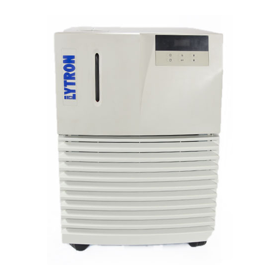
Advertisement
Advertisement
Table of Contents

Related Manuals for Kodiak RC045

Summarization of Contents
INTRODUCTION
Receiving the New Chiller
Instructions for inspecting a new chiller upon receipt and handling shipping damage claims.
Warranty and Customer Support
Details on warranty claims, requiring an RMA, and contact info for service support.
SAFETY PRECAUTIONS
General Safety Instructions
Important warnings and instructions for safe operation and maintenance.
Fluid Handling and Operation Warnings
Precautions regarding coolant type, location, grounding, and unit operation.
LABELS AND SILKSCREEN MARKING
Safety and Warning Symbols
Explanation of warning symbols for operating and electrical hazards.
Functional and Certification Markings
Description of labels for connections, RS-232, and safety certifications.
PRODUCT IDENTIFICATION AND CERTIFICATIONS
Product ID Label Details
Information provided on the product ID label including model, serial, and electrical data.
Disposal and RoHS Compliance
Explanation of disposal symbols and RoHS compliance marking.
PART NUMBER DESCRIPTION
Model and Configuration Breakdown
Explains the breakdown of part numbers based on model, electrical, and pump configurations.
Controller Package Options
Details the features included in Controller Packages 1, 2, and 3.
SPECIFICATIONS
Thermal Capacity and Electrical Ratings
Specifies thermal capacity, BTU/hr, voltage, and amperage for each model.
Physical and Environmental Specifications
Details compressor size, refrigerant, temperature stability, and coolant range.
Dimensions, Connections, and Weight
Lists unit dimensions, connection types, weight, and process coolant delivery pressure.
PERFORMANCE GRAPHS
RC006-RC011 Performance Curves
Graphs showing cooling capacity vs. output temperature for RC006 to RC011 models.
RC022-RC045 Performance Curves
Graphs showing cooling capacity vs. output temperature for RC022 to RC045 models.
GENERAL INFORMATION
Chiller System Description
Overview of the chiller's components and fluid flow path.
Coolant Loop and Refrigeration Systems
Explains the closed-loop coolant system and the hot-gas bypass for temp control.
CONTROLLER DISPLAY PANEL FUNCTIONS
Controller Display Layout and Keys
Diagram identifying the display, buttons, and indicators on the controller panel.
Controller Key Operations
Table explaining the function of each button on the controller keypad.
Indicator Descriptions
Explanation of the meaning of each indicator light on the controller display.
REAR PANEL COMPONENTS
Power, Circuit Breaker, and Contacts
Identifies the power entry, circuit breaker, and external contacts on the rear panel.
Fluid and Communication Ports
Locates the supply/return fluid connections and RS-232 port on the rear panel.
OPTIONAL SYSTEM FEATURES
Filtration, Deionization, and External Contacts
Describes coolant filter, deionization package, and external customer contacts.
Flow Control, Pressure Relief, and Shutoff
Explains adjustable flow valve, pressure relief valve, and fault shut-off options.
Heater, High Purity, and Remote Start
Details the heater package, high purity plumbing, and remote start options.
ADDITIONAL OPTIONAL FEATURES
RS-232 Serial Port Communication
Describes remote chiller control via RS-232 port and available software.
Water Cooled Condenser Option
Details the water-cooled condenser option, its requirements, and flow rates.
CONTROLLER OPTIONS
Controller Package #1 Features
Lists the standard features included in Controller Package #1.
Controller Package #2 Features
Lists the standard features included in Controller Package #2.
Controller Package #3 Features
Lists the features of Controller Package #3, including RS-232.
INSTALLATION REQUIREMENTS
Coolant Requirements and Recommendations
Specifies coolant type, freezing point depressants, and water quality.
Electrical Requirements
Details power cord type and electrical requirements for units without a heater.
Chiller Location Selection
Guidelines for selecting an optimal location, considering airflow and proximity.
INSTALLATION PROCEDURE
Hose Selection and Routing
Guidance on selecting and routing coolant hoses for minimal pressure loss and heat gain.
Connecting Plumbing and Filling
Step-by-step instructions for connecting fluid lines and filling the reservoir.
PRIMING TURBINE AND CENTRIFUGAL PUMPS
Pump Priming Importance and Conditions
Explains why pumps must be primed and the conditions requiring priming.
Pump Priming Procedures
Steps for priming pumps using the integrated valve or alternative methods.
CONNECTING POWER AND STARTUP
Power Connection and Grounding
Instructions for connecting the power cord and ensuring proper grounding.
Chiller Startup Procedure
Steps to turn on the chiller, adjust set points, and check for leaks.
CHILLER OPERATION AND CONTROLLER SETTINGS
Customer Menu Options Overview
Introduces the customer menu and available settings for operation.
Temperature and Pressure Unit Settings
Configuration for displaying temperature in Celsius/Fahrenheit and pressure in bar/psi.
Alarm and Fault Indication Settings
Details settings for over-temperature, low-temperature, and audible alarms.
DETAILED CONTROLLER CONFIGURATIONS
Audible Alarm, Auto Restart, and Calibration
Configuration steps for audible alarms, auto-restart, and calibration offset.
Temperature Scale and Fault Shutoff
Instructions for changing the temperature display scale and configuring fault shutoff.
Low Temperature Indication Settings
Configuration for the low temperature indication threshold.
ADVANCED CONTROLLER SETTINGS
Over Temperature and Pressure Unit Settings
Setting the over-temperature indication and configuring pressure units.
Remote Start and User Control Flags
Configuration for the remote start feature and user control flags.
SYSTEM MAINTENANCE AND SERVICE
General Maintenance and Inspections
Overview of periodic inspections and general care for the chiller.
Component Specific Maintenance
Maintenance for pump, fan, condenser fins, water filter, and deionization package.
Low Level Switch and Filter Checks
Procedure for checking the low level switch and water filter.
COOLANT AND CLEANING PROCEDURES
Algae Prevention and Cleaning the System
Recommendation for algae inhibitor and steps for cleaning the chiller system.
Pump Strainer and Pump Replacement
Instructions for cleaning the pump strainer and pump replacement guidance.
DRAINING PROCEDURE FOR KODIAK CHILLERS
Recommended Draining Method (Wet/Vac)
Detailed steps for draining the chiller using a wet/vac.
Alternative Draining Method (Gravity)
Steps for draining the chiller without a wet/vac, relying on gravity.
COOLANT MAINTENANCE
Recommended Coolant Usage and Checks
Guidelines for coolant type, mixing with glycol, and checking coolant level.
Flushing and Replacing Coolant
Procedure for periodic flushing and replacement of chiller coolant.
ERROR CODES
Controller Initialization and RTD Errors
Explanation of Err 01 (Controller Initialization) and Err 02 (RTD) errors.
Operational, Flow, and Remote Start Errors
Explanation of Err 03 (Operational), Err 04 (Low Flow), and Err 05 (Remote Start) errors.
Auto Temperature Shut Down Error
Explanation of Err 07 (Auto Temp Shut Down) error.
TROUBLE SHOOTING GUIDE
Startup, Noise, and Pressure Issues
Troubleshooting for startup failures, noise, excessive pressure, and compressor issues.
Motor, Alarm, and Flow Problems
Troubleshooting for pump motor, audible alarms, and low coolant flow issues.
ADDITIONAL TROUBLESHOOTING
Low Coolant Flow and Shutdowns
Diagnosing and resolving issues related to low coolant flow and chiller shutdowns.
Display and Pressure Issues
Troubleshooting for incorrect temperature display readings and high pressure.
KODIAK SPARE PARTS
Controller and Electrical Components
List of part numbers for controller PCBs, circuit breakers, and relays.
Mechanical, Fluid, and Refrigeration Parts
Part numbers for tanks, sensors, valves, heat exchangers, and compressor/fan.
ACCESSORIES AND REPLACEMENT PARTS
Pumps, Motors, and Filters
Part numbers for various pump and motor combinations, and filter kits.
Air Filters and Pressure Relief Kits
Part numbers for air filters and external pressure relief kits.
FRONT VIEW COMPONENT IDENTIFICATION
Front Panel and Control Interface
Labels identifying the keypad, access panel, and upper front section.
Chiller Grille and Mobility Features
Identification of the front grille and caster assembly.
REAR VIEW (WITH PANEL)
Circuit Breaker and Rear Panel Components
Locates the circuit breaker and identifies various rear panel components.
TOP VIEW INTERNAL COMPONENTS
Reservoir, Pump, and Motor Assembly
Identifies the tank, pump, motor, and related components from the top view.
Sensors, Relays, and Flow Switch
Locates temperature sensors, flow switches, and pump/compressor relays.
REAR VIEW (OPENED)
Refrigeration System Components
Identifies the hot gas bypass valve, heat exchanger, and capillary tube.
Flow Switch Location
Pinpoints the location of the flow switch within the rear view.
SIDE VIEW INTERNAL COMPONENTS
Compressor, Condenser, and Solenoid Valve
Identifies the compressor, condenser, and solenoid valve.
Filter Dryer and Flow Switch
Locates the liquid line filter dryer and flow switch on the side view.
SIDE VIEW (HIGH PRESSURE CUTOUT)
High Pressure Cutout and Reset Button
Highlights the location of the high pressure cutout and reset button.
DIMENSIONS FOR RC006 AND RC009
Overall Dimensions and Component Legend
Provides overall dimensions and a legend for components.
Rear View Component Locations
Shows the location of rear components like the circuit breaker and water filter.
DIMENSIONS FOR RC011 AND RC022
Overall Dimensions and Component Legend
Provides overall dimensions and a legend for components.
Rear View Component Locations
Shows the location of rear components like the circuit breaker and water filter.
DIMENSIONS FOR RC030 AND RC045
Overall Dimensions and Component Legend
Provides overall dimensions and a legend for components.
Rear View Component Locations
Shows the location of rear components like the circuit breaker and water filter.
WIRING DIAGRAM
Main Harness and Connections
Details the main wiring harness, connectors, and component interconnections.
Voltage Configuration and Notes
Explains voltage configuration options and important notes on the wiring.
PLUMBING DIAGRAM
Coolant Flow Path and Components
Diagram illustrating the flow of coolant through the system components.
Optional Component Integration
Shows the integration of optional features like water filters and deionization cartridges.
REFRIGERATION DIAGRAM
Refrigerant Circuit Components
Illustrates the refrigerant flow path and major components like evaporator and condenser.
Hot Gas Bypass System Details
Details the hot gas bypass valve and its role in temperature control.
HOST INTERFACE DATA LINK
Port Settings and Flow Control
Specifies RS-232 port settings and flow control mechanisms.
Message Encoding and Numeric Representation
Details ASCII character encoding and numeric representation for data transfer.
HOST INTERFACE COMMANDS
Reading Chiller Status and Temperature
Defines commands for reading chiller status, alarm flags, and plant temperature.
Reading Set Point and User Configuration
Commands for retrieving set point temperature and user menu configuration.
HOST INTERFACE CONTROL COMMANDS
Setting Plant Setpoint and Over-temperature
Commands to set plant setpoint temperature and optional over-temperature limit.
Setting Low Temperature and Offset
Commands to set low temperature alarm limit and offset calibration.
Setting User Control Flags
Commands for setting user control flags like power, display, and auto-start.
LYTRON COOLING SYSTEMS SERVICE POLICY
Diagnostic Consultation and Support
Information on phone diagnosis, customer support, and service availability.
Warranty and Non-Warranty Returns
Procedures for returning units for evaluation, repair, and associated fees.
SERVICE OPERATIONS AND REPLACEMENT PARTS
Field Service and Installation Charges
Details on field service availability, charges, and warranty coverage.
Replacement Parts Ordering and Warranty
Information on ordering replacement parts, warranty claims, and shipping.
LYTRON KODIAK RECIRCULATING CHILLER STANDARD WARRANTY
Warranty Coverage and Obligations
Defines warranty period, obligations, and exclusions for defects.
Warranty Exclusions and Limitations
Details what is not covered by the warranty, including labor and consequential damages.
DECLARATION OF CONFORMITY
Product and Directive Compliance
Declaration of conformity for Kodiak Recirculating Chiller with EU directives.
Standards and Quality System Compliance
Lists conformity to EN standards and compliance with ISO 9001:2008.
Need help?
Do you have a question about the RC045 and is the answer not in the manual?
Questions and answers