Table of Contents
Advertisement
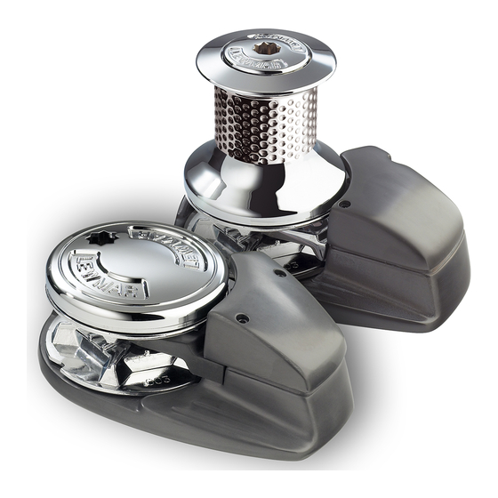
Concept/Ocean/Capstan 1, 2 & 3
Windlass Range
OWNERS INSTALLATION, OPERATION AND SERVICE MANUAL
INSTALLATIONS-, BEDIENUNGS- UND WARTUNGSHANDBUCH FUR BOOTEIGENTUMER
MANUAL DU PROPRIETAIRE, INSTALLATION, MISE EN SERVICE ET ENTRETIEN
MANUAL DEL PROPIETARIO. INSTALACION, FUNCIONAMIENTO Y MANTENIMIENTO
INSTALLATIONS, INSTRUKTIONS SAMT SERVICE MANUAL
Issue 5
Advertisement
Table of Contents

Summarization of Contents
Electric Wiring Installation
Wiring Details and Control Box Mounting
Details on wiring and mounting control boxes or solenoid switches near the windlass.
Electric Cable Routing and Connection
Planning and installing electric cables from motor to control box, and to circuit breaker and battery.
Safety Switch and Remote Control Placement
Positioning and connecting safety switches, remote control, and rocker switches.
Battery Cable Connection and Protection
Connecting battery cables, securing connections, and using rubber boots for protection.
Windlass Operation and Rotation Check
Verifying the windlass operation and correct rotation direction (up/down).
Thermal Cutout Connection
Ensuring that a thermal cutout is properly connected for safety.
Wiring Data and Cable Sizes
Cable Size Recommendations
Recommended cable sizes and types for windlass installation and performance.
Cable Specifications and Voltage Drop
Details on terminals, performance relation to cable size/length, voltage drop, and circuit breaker placement.
Hydraulic Line Installation
Hydraulic System Compatibility and Hose Routing
Using Commander powerpacks, routing hydraulic lines, and selecting hose sizes.
Hydraulic Connection to Motor
Securely connecting hydraulic feed and supply lines to the windlass motor.
Control Switch Wiring for Hydraulic System
Positioning and connecting switches to Commander system or similar, noting 3 amp minimum supply.
Hydraulic Pressure Limits and Safety
Setting maximum pressure to 100 bar (1450 psi) to prevent windlass damage.
Hydraulic Windlass Operation Check
Verifying proper operation and rotation direction of the hydraulic windlass.
Hydraulic Data and System Specifications
Hydraulic Performance and Safety Notes
Notes on performance, hose size, motor rotation, check valve, pressure limits, and drain line.
Operating Your Windlass
Basic Operation: Up and Down Controls
Instructions for operating the windlass using the UP and DOWN switches.
Manual Chain Release Procedure
Steps for manually releasing and controlling chain descent.
Capstan Operation Modes
Using the capstan independently by tying off rope/chain or using the gypsy pawl.
Emergency Manual Override (Ocean Range)
Procedure for emergency manual override on Ocean range models.
Capstan Only Unit Operation
Operating capstan-only units and their limitations.
Important Operating Notes and Tightening
Notes on ensuring the top nut is tight and proper tightening procedure.
Windlass Maintenance
Above Deck Maintenance
Disassembling, cleaning, and oiling above-deck parts every 6 months.
Below Deck Component Maintenance
Checking motor/gearbox condition, terminals, and repainting if corrosion is evident.
Rope and Chain Combinations
Compatible Rope and Chain Types
Information on using 3-strand Nylon rope spliced to calibrated chain and compatibility.
Rope and Chain Splice Procedure
Recommended Splice Method
Using a 3 or 4 tuck back splice with 3-strand nylon rope for chain attachment.
Step-by-Step Splice Instructions
Detailed steps for creating a rope and chain splice, including seizing and cutting.
Splice Inspection and Wear
Importance of regular inspection and reworking of splices due to extreme usage.
Performance Diagrams
Concept/Ocean/Capstan 1 Performance Data
Graphs showing line speed and current draw for 12V and 24V versions.
Concept/Ocean/Capstan 2 Performance Data
Graphs showing line speed and current draw for 12V and 24V versions.
Performance Diagrams (Continued)
Concept/Ocean/Capstan 3 Electric Performance
Graphs detailing line speed and current draw for the 12V/24V model.
Concept/Ocean 2 & 3 Hydraulic Performance
Graphs showing flow rate and pressure for hydraulic models.
Electrical Connections and Wiring Diagrams
Wiring Diagram: Concept/Ocean 1 & 2 Dual Direction
Wiring diagram for dual-direction control box on Concept/Ocean 1 & 2 models.
Wiring Diagram: Concept/Ocean/Capstan 1 & 2 Single Direction
Wiring diagram for single-direction control box on Concept/Ocean/Capstan 1 & 2 models.
Electrical Connections and Wiring Diagrams (Continued)
Wiring Diagram: Concept/Ocean 1 & 2 Contactor Dual Direction
Contactor wiring diagram for dual-direction control on Concept/Ocean 1 & 2.
Wiring Diagram: Concept/Ocean/Capstan 1 & 2 Solenoid Switch
Solenoid switch wiring diagram for single and dual direction on Concept/Ocean/Capstan 1 & 2.
Electrical Connections and Wiring Diagrams (Concept/Ocean 3)
Wiring Diagram: Concept/Ocean 3 Dual Direction Control Box
Control box wiring for dual-direction Concept/Ocean 3 models.
Wiring Diagram: Concept/Ocean/Capstan 3 Single Direction Control Box
Control box wiring for single-direction Concept/Ocean/Capstan 3 models.
Electrical Connections and Wiring Diagrams (Concept/Ocean 3 - Contactor/Solenoid)
Wiring Diagram: Concept/Ocean 3 Contactor Dual Direction
Contactor wiring diagram for dual-direction control on Concept/Ocean 3.
Wiring Diagram: Concept/Ocean/Capstan 3 Solenoid Switch Single Direction
Solenoid switch wiring for single-direction control on Concept/Ocean/Capstan 3.
Fault Finding and Troubleshooting
Troubleshooting Checklist Questions
A series of diagnostic questions to identify windlass operational issues.
Troubleshooting Action Steps
Actionable steps to resolve windlass problems based on checklist answers.


Need help?
Do you have a question about the Ocean 2 and is the answer not in the manual?
Questions and answers