Table of Contents
Advertisement
Mains Powered
Ei3024 / 3016 / 3014
Alarms
Instruction Manual
Read and retain carefully for as long as the product is being used. It contains vital
information on the operation and installation of your Alarm. The leaflet should be
regarded as part of the product.
If you are just installing the unit, the leaflet MUST be given to the householder. The
leaflet is to be given to any subsequent user.
Advertisement
Table of Contents

Related Manuals for EI 3014


Summary of Contents for EI 3014
- Page 1 Mains Powered Ei3024 / 3016 / 3014 Alarms Instruction Manual Read and retain carefully for as long as the product is being used. It contains vital information on the operation and installation of your Alarm. The leaflet should be regarded as part of the product.
-
Page 2: Table Of Contents
Contents Installer Guide 1. Introduction 1.1 Overview 1.2 Technical Specifications 2. Installation 2.1 Important Safety Instructions 2.2 Where to locate the Alarm? 2.3 Which Alarm in what room? 2.4 Where in the room? 2.5 Locations to avoid 2.6 Mounting and wiring 2.7 Interconnecting Alarms 2.8 Removing the Alarm... - Page 3 User Guide 3. Testing 3.1 Testing and maintaining your Alarm 3.2 Cleaning your Alarm 4. What to do in case of alarm 5. Troubleshooting and Indicator summary tables 6. Important safeguards 7. Service and Guarantee Getting your Alarm serviced 7.2 Guarantee...
-
Page 4: Installer Guide
Installer Guide Introduction... - Page 5 The Ei3014 is a Heat Alarm with a Class A1 heat detection sensor. It can only to be used as part of a fire detection system, i.e. interconnected with Ei Electronics mains powered Multi-Sensor Fire or Smoke Alarms. It is ideal for kitchens, garages, boiler houses and other areas where there are normally high levels of fumes, smoke or dust i.e.
-
Page 6: Overview
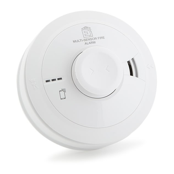
1.1 Overview Ei3024 Multi-Sensor Fire Alarm Green LED Test / Hush Button Alarm Sounder Power Indicator Smoke Entry Vents Yellow LED Fault Indicator Heat Sensor Red LED (Thermistor) Alarm Indicator Alarm Removal Latch RF Module LED Indicator RF Module Learn Switch... - Page 7 Ei3016 Optical Alarm Ei3014 Heat Alarm Smoke Entry Vents Heat Sensor (Thermistor) Alarm Alarm Removal Removal Latch Latch RF Module RF Module LED Indicator LED Indicator RF Module RF Module Learn Switch Learn Switch...
-
Page 8: Technical Specifications
1.2 Technical Specifications Optical Sensor Optical (Ei3024 and Ei3016) Heat Sensor Thermistor Class A1 Detection (Ei3014 and Ei3024) Power Supply 100-250V AC, 50Hz, 0.25W Built-in 10-year rechargeable Vanadium Pentoxide Lithium cells. Fully Battery Backup charged, the battery will provide up to 6 months (without module fitted) or 3 months (with module fitted) back-up without mains power Alarm Sounder Piezoelectric Horn... - Page 9 Technical Specifications Supplied with Easi-fit anti-tamper mounting plate with integral Fixings terminal block and wiring cover, includes screws and wall plugs Operating Temperature Normal: 0°C to +40°C (Storage: 0°C to +40°C)* Humidity Range 15% to 95% RH (non-condensing) Plastic Material UL94V-0 flame retardant rated Ei3024 and Ei3014: Product: - Ø150mm x 66mm Package - 155mm x 155mm x 70mm...
-
Page 10: Installation
Installation... -
Page 11: Important Safety Instructions
2.1 Important Safety Instructions Mains operated Alarms should be installed and interconnected by a qualified electrician in accordance with the local appropriate Regulations for Electrical Installations. Failure to install this Alarm correctly may expose the user to shock or fire hazards and damage the product. The Alarm is designed to be permanently mounted, using its own built-in terminal block to connect it to the mains. -
Page 12: Where To Locate The Alarm
The Alarm must be continuously powered 24 hours a day so it is important that it is not on a circuit that can be turned off by a switch. (UK) BS 5839-6: 2013 gives the following recommendations regarding the mains supply to be used in a Grade D system. - Page 13 The greater the risks, the more comprehensive and reliable systems needs to be. LD (Life protection in Dwellings) Systems define the level of fire protection required for households, depending on the fire risk and regulations. Ei Electronics recommends that an LD1 system be installed for optimum protection.
- Page 14 UK Requirements (BS 5839-6:2013) OPTIMUM PROTECTION for dwellings where occupants may be at high risk (e.g. elderly) Optimum Protection LD1: As LD2, but in addition Smoke or Heat Alarms should be located in all rooms and other areas of the dwelling. (apart from toilets or bathroom) Interconnect all Alarms BASIC PROTECTION...
- Page 15 ROI Requirements (IS 3218:2013) OPTIMUM PROTECTION for dwellings where occupants may be at high risk (e.g. elderly) Optimum Protection LD1: As LD2, but also including attics / lofts / other spaces in which a fire might start (apart from toilets or bathroom). Interconnect all Alarms BASIC PROTECTION for new or materially altered dwellings or existing dwellings...
-
Page 16: Which Alarm In What Room
2.3 Which Alarm in what room? Location Ei3024 Ei3016 Ei3014 Mutil-Sensor Optical Heat Fire Alarm Smoke Alarm Alarm (i) Hall, Corridors, Escape routes Kitchens / Garages Living Rooms Bedrooms Shower / Bathrooms (i) A Heat Alarm should only be used in a room adjoining an escape route, in conjunction with Multi-Sensor Fire Alarms or Smoke Alarms on the escape routes. - Page 17 Improved Audibility The effectiveness of a Category LD2 (UK) system can be significantly enhanced if an additional Alarm (interconnected) is installed in the master bedroom. This will help ensure that a responsible person will quickly be alerted to a fire and can arrange for an orderly evacuation of children and other vulnerable occupants.
-
Page 18: Where In The Room
2.4 Where in the room? The locations must comply with applicable building regulations 300mm (min) Ceiling Mounting Hot smoke rises and spreads out, so a central ceiling position is the preferred location. The air is “dead” and does not move in corners, therefore Alarms must be mounted away 300mm from corners. -
Page 19: Locations To Avoid
Wall mounting should only be considered where close spaced beams or similar obstructions may preclude ceiling mounting. It is considered to be the responsibility of the installer/client to determine if the presence of asbestos in the ceiling material would make ceiling mounting ‘impractical’. Sloping Ceiling APEX SMOKE /... - Page 20 • Next to or directly above heaters or air conditioning vents, windows, wall vents etc. where air draughts can change the direction of airflow and cause rapid temperature fluctuations. • In very high or awkward areas (e.g. over stairwells) where it may be difficult to reach the Alarm (for testing, hushing etc.).
-
Page 21: Mounting And Wiring
2.6 Mounting and wiring 1. Select a location complying with the advice in previous sections. 2. Disconnect the AC mains supply from the circuit that is going to be used. 3. Lift off the wiring cover as shown in Figure 4. The wiring must be connected to the terminal Foam ceiling gasket block on the mounting plate as follows:... - Page 22 Warning: Mixing (or leaving unattached) the Live and Neutral connections when interconnecting Alarms may damage all the Alarms - ensure that the same colour wires are used throughout the premises for Live, Neutral and Interconnect wires. We strongly recommend that you check for the following before connecting the Alarm: •...
- Page 23 Fig.5 Fig.6 4. If the mains wires are recessed, bring the wires through the rear hole in the mounting plate as shown in Figure 5. If the mains wires are being brought along the surface: (a) position the mounting plate so the cable trunking is as shown in Figure 5. (b) the mounting plate has a removable section, take it out to interface directly with 25mm trunking as shown in Figure 6.
- Page 24 6. Replace the wiring cover and carefully line up the Alarm on the base and slide on (see Figure 7). 7. Connect the mains power to the Alarm circuit. Check the green light on the front of the Alarm is on. 8.
-
Page 25: Interconnecting Alarms
Note: A maximum of 12 Fire / Smoke / Heat / CO Alarms and accessory devices can be interconnected in an Ei Electronics Alarm system. (Any Ei3000 series Alarm can also be interconnected to an Ei2110e, Ei160e and Ei140RC Series). - Page 26 Make electrical connections as shown in Figure 9. Wiring must be installed in compliance with Fig.9 local regulations. In the UK and Ireland it is recommended that the following coloured cores are used (for example with triple flat 6243YH cable). 230V supply : Brown Neutral : sleeved blue at terminations Interconnect : Black...
-
Page 27: Removing The Alarm
Please note in a hybrid system containing CO / Heat / Fire / Smoke Alarms we recommend using an Ei3000 series Alarm as the hybrid link to the RF section of the system. Ensure the Alarms operate correctly - see TESTING YOUR ALARM in the user section. 2.8 Removing the Alarm * Disconnect mains before removal * Locate removal slot... -
Page 28: User Guide
User Guide Testing... -
Page 29: Testing And Maintaining Your Alarm
3.1 Testing and maintaining your Alarm Frequent testing of all your Alarms is a requirement to ensure they are functioning correctly. Guidelines and best practices for testing are as follows: 1. After the system is installed. 2. Once monthly thereafter. 3. - Page 30 (iii) Press the test button for up to 10 seconds and ensure that the Alarm sounds. This tests the sensor, electronics and sounder are working. The Alarm will stop when the button is released. Pressing the test button simulates the effect of smoke and/or heat and therefore is the best way to ensure the Alarm is operating correctly.
-
Page 31: Cleaning Your Alarm
The Ei3000MRF modules (if required) must be re-fitted to the Alarms and the Alarms must be re-attached to the mounting plates when the premises are re-occupied. Ensure to match the original RF module back to the same Alarm head. (Long term storage (over 1 year) can damage the batteries such that they will not recharge when the units are re-connected to the mains supply). - Page 32 WARNING: Do not paint your Alarm. Other than the cleaning described above, no other customer servicing of this product is required. Servicing or repairs, when needed, must be performed by the manufacturer. All Alarms are prone to dust and insect ingress, which can cause false alarms or failure to alarm. In certain circumstances, even with regular cleaning, contamination can build up in the smoke sensing chamber causing the Alarm to sound or fail.
-
Page 33: What To Do In Case Of Alarm
What to do in case of alarm... - Page 34 (i). Check room doors for heat or smoke. Do not open a hot door. Use an alternate escape route. Close all doors behind you as you leave. (ii). If smoke is heavy, crawl out, staying close to floor. Take short breaths, if possible, through a wet cloth or hold your breath.
-
Page 35: Troubleshooting And Indicator Summary Tables
Troubleshooting Indicator summary tables... - Page 36 Your Alarm does not • Check the Alarm is secured correctly on the mounting plate. • Wait 15 seconds after connecting the power before button testing. sound when you press the Test button • Hold button down firmly for at least 10 seconds. •...
- Page 37 Interconnected Alarms • Hold test button for at least 10 seconds to ensure that the signal is transmitted to all the interconnected Alarms. do not all sound • If this is not the case and you have a hardwired interconnection, we recommend you consult a qualified electrician.
- Page 38 Normal mode Mode Action Green LED Yellow LED Red LED Sound (power) (fault) (alarm) Power up Slide onto mounting plate Standby Testing Press and hold (monthly) test button In alarm mode Detecting fire Activated via interconnect Pressing Silence Button on Alarm detecting fire x 10mins With the test button held the green LED will flicker/pulse every second...
- Page 39 Memory mode Status Action Red LED Sound (alarm) 0-24h every 48 sec every >24h + Press and hold test button 8 sec To erase the Sounds until test button Keep test button pressed for >20s memory is released The Alarm memory is an important feature where even if the house is unoccupied during an alarm condition it warns the homeowner that the Alarm has previously detected Fire and been in alarm.
- Page 40 Fault modes and Memory indicator What you hear / see What it What to do Green LED Yellow LED Red LED Chirps means (power) (fault) (alarm) every Reconnect AC AC mains off 48 sec mains power AC mains off every Reconnect AC Low battery 48 sec...
- Page 41 The Alarm can communicate its status and history through various Led flashes and chirps/beeps. However, a more comprehensive report of all such events is available through the AudioLINK download via the App. Low Battery Backup Fault If the battery backup supply is depleted, the sounder will give one short chirp with one yellow LED fault indicator flash every 48 seconds.
- Page 42 The entire Alarm must be replaced (Also check the replace by date on the label on the side of the Alarm). Disconnect the mains first and replace the Alarm - see ‚Removing the Alarm‘ section. Maximum Dust Compensation (Ei3016 and Ei3024 only) The Alarm monitors the dust contamination build-up in the optical smoke chamber and then compensates for it, reducing the possibility of false alarms.
-
Page 43: Important Safeguards
Important safeguards... - Page 44 Limitations of Fire Alarms Multi-Sensor Fire / Smoke / Heat Alarms can significantly help to reduce the risk of fire fatalities. However independent authorities have stated that these systems may be ineffective in some fire situations. There are a number of reasons for this: - The Alarms will not work if the mains power supply is off or disconnected and the backup battery is depleted.
- Page 45 When a fire system is installed, basic safety precautions should always be followed, including those listed below: • Please read all instructions. • Use the Testing of the Alarm as a means to familiarise your family with the alarm sound and to practice fire drills regularly with all family members.
-
Page 46: Service And Guarantee
Service and Guarantee... -
Page 47: Getting Your Alarm Serviced
7.2 Guarantee Ei Electronics guarantees this Alarm for five years from the date of purchase against any defects that are due to faulty materials or workmanship. If this Alarm should become defective within the guarantee period, we shall at our discretion repair or replace the faulty unit. - Page 48 The crossed out wheelie bin symbol that is on your product indicates that this product should not be disposed of via the normal household waste stream. Proper disposal will prevent possible harm to the environment or to human health. When disposing of this product please separate it from other waste streams to ensure that it can be recycled in an environmentally sound manner.
- Page 49 0086 Ei Electronics, Shannon, Co. Clare, Ireland DoP No.18-0001 EN14604:2005 + AC:2008 Smoke Alarm Devices: Ei3016, Ei3024 Fire Safety Nominal activation conditions/ sensitivity, Pass Vibration resistance Pass response delay (response time) and performance under fire condition Operational reliability Pass Humidity resistance...
- Page 50 KM522831 KM83678 EN14604:2005+AC 2008 BS5446-2:2003...
- Page 52 Aico Ltd. Mile End Business Park, Maesbury Rd, Oswestry, Shropshire SY10 8NN, U.K. Tel: 01691 664100 www.aico.co.uk Ei Electronics. Shannon, Co Clare, Ireland. Tel:+353 (0)61 471277 P/N B18660 Rev0 www.eielectronics.com © Ei Electronics 2018...
Need help?
Do you have a question about the 3014 and is the answer not in the manual?
Questions and answers