Table of Contents
Advertisement
Flame Safeguard Programming Controls
OPTIONAL
202050C
COVER
OPTIONAL HEAVY DUTY
COVER (PART NO.
202050C OR 139695C)
IMPORTANT
Applications, Features, Specifications (including
dimension drawings), Operation (including
schematics and bar charts), and Wiring Diagrams
are included in these Specifications for models of
the R4140G, L, and M: R4140G—60-2337;
R4140L—60-2339; R4140M—60-2340.
Copyright © 1996 Honeywell Inc. • All Rights Reserved
RESET BUTTON
TIP JACK
PLUG-IN
AMPLIFIER
RELAY/TIMER
COVER
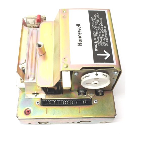
Fig. 1. Components of R4140G and R4140M Programmers.
RESET BUTTON
PLUG-IN
FLAME SIGNAL
AMPLIFIER
FLAME SIGNAL
METER JACK
RELAY/TIMER
COVER
Fig. 2. Components of R4140L Programmers.
R4140G,L and M
HANDLE
TIMER
TIMER DIAL
RELAY
FLAME SIGNAL
2K
METER JACK
CHASSIS RETAINING
HANDLE
TIP JACK
SCREW
TIMER
TIMER DIAL
RELAY
2K
RELAY 1K
Installation ........................................................................... 2
Checkout ............................................................................. 11
Troubleshooting .................................................................. 18
Service Information ............................................................. 27
Testing and Maintenance .................................................... 28
INSTALLATION INSTRUCTIONS
CHASSIS RETAINING
SCREW
SAFETY SWITCH
BUTTON
CHASSIS
HINGE
TIMER
BRACKET (2)
MOTOR
RELAY
1K
M10053
RELAY 4K
SAFETY SWITCH
BUTTON
CHASSIS
HINGE
BRACKET (2)
TIMER
RELAY
MOTOR
M7959
3K
Contents
60-0770-2
Advertisement
Table of Contents
Troubleshooting

Related Manuals for Honeywell R4140L


Summarization of Contents
Honeywell R4140 Flame Safeguard Programming Controls Installation
Location Considerations for Installation
Guidance on selecting an appropriate installation site for the R4140 based on environmental factors like temperature and humidity.
Weather Protection Requirements
Information regarding protection requirements for outdoor installations of the R4140.
Mounting the Wiring Subbase
Instructions on how to physically mount the subbase for the R4140 programmer, including orientation constraints.
Wiring to Subbase
Details and precautions for connecting wires to the R4140 subbase, including wire type and safety notes.
Installing the Flame Detector
Guidance on the proper installation of flame detectors for reliable operation and safety.
Special Considerations for C7012E or F Detectors
Specific installation advice for C7012E or F ultraviolet flame detectors, including power requirements.
Using Redundant Parallel C7012E or F Detectors
Instructions for wiring multiple C7012E or F detectors in parallel for improved flame detection reliability.
Static Checkout Procedures
Equipment Required for Static Checkout
List of tools and equipment needed for performing static checkout procedures.
General Instructions for Static Checkout
Important guidelines and steps to follow before and during the static checkout process.
Programmer Installation and Removal Procedures
Installing the Programmer
Step-by-step guide for physically installing the R4140 programmer onto its subbase.
Removing the Programmer
Instructions on how to safely detach the R4140 programmer from its subbase.
Programmer Servicing Procedures
Removing and Replacing the Relay/Timer Cover
Steps for accessing internal components by removing and reinstalling the programmer's cover.
Installing a Plug-in Flame Signal Amplifier
Guide on how to insert and secure a flame signal amplifier module into the programmer.
Installation Instructions for Special Features
Information on special features available on certain R4140 models.
Programmer Configuration and Upgrades
Installing Jumper on Back of Programmer
Instructions for installing a jumper to extend the main burner flame-establishing period.
Upgrading Systems
Information on selecting R4140 models for different application requirements and system upgrades.
Model Replacement and Wiring Diagrams
Replacing an R4140M with an R4140G
Wiring diagrams and instructions for replacing an R4140M with an R4140G model.
Replacing an R4140M or G with an R4140L
Wiring diagrams and instructions for replacing an R4140M or G with an R4140L model.
Checkout Procedures
Equipment Required for Checkout
List of tools and instruments necessary for performing checkout tests.
Checkout Summary
Overview of all checkout tests required for various installation types.
Preliminary Inspection (All Installations)
Initial checks to perform on all installations to prevent common problems.
Flame Signal Measurement
Procedure for measuring flame signal strength using test equipment.
Initial Lightoff Check for Proved Pilot
Test procedure to verify pilot ignition and signal before main burner operation.
Initial Lightoff Check for Direct Spark Ignition of Oil
Checkout procedure for oil burners without a pilot, focusing on direct spark ignition.
Pilot Turndown Test
Procedure to test pilot flame stability by reducing gas pressure until relay dropout.
Ignition Interference Test
Verifies that ignition spark does not falsely trigger the flame signal.
Hot Refractory Saturation Test
Checks if hot refractory radiation masks the flame signal.
Hot Refractory Hold-In Test
Ensures hot refractory does not keep the flame relay energized after flame loss.
Ultraviolet Response Tests
Tests response of ultraviolet detectors to ignition spark and other light sources.
Flame Signal with Hot Combustion Chamber
Measures flame signal under hot conditions and checks response time.
Safety Shutdown Tests (All Installations)
Verifies system safety shutdown occurs correctly under various failure conditions.
Troubleshooting Procedures
Troubleshooting Equipment Required
Lists essential tools and equipment for diagnosing and resolving system issues.
Preliminary Check for Troubleshooting
Initial checks to perform to rule out common causes of programmer malfunction.
Troubleshooting Chart and Procedures
Guidance on diagnosing and resolving specific system symptoms using the troubleshooting chart.
Flame Relay (2K) Hold-In Check
Procedure to test if the flame relay stays energized after flame loss.
Service Information and Maintenance
Scheduled Inspection and Maintenance
Recommended schedule for inspecting, maintaining, and testing controls.
Contact Cleaning Guidelines
Guidelines and warnings regarding the cleaning of relay and timer contacts.
Testing and Maintenance Schedule
Minimum Inspection and Testing Schedule
A table outlining recommended inspection and testing frequencies for boiler controls.
CM-102 Minimum Schedule Details
Detailed breakdown of inspection tasks by frequency (Daily, Weekly, Monthly, etc.).
Cm-103 General Guidance
General guidance emphasizing adherence to manufacturer's specific instructions.
Need help?
Do you have a question about the R4140L and is the answer not in the manual?
Questions and answers