Table of Contents
Advertisement
Advertisement
Table of Contents

Related Manuals for Deif PPM

Summarization of Contents
Document Overview and Safety Information
Document Purpose and Intended Users
Explains the document's scope and target audience.
Definitions of Notes and Warnings
Clarifies the meaning of notes and warnings used throughout the manual.
Safety, Legal, and ESD Precautions
Legal Information and Responsibility Disclaimer
Outlines DEIF's responsibility and legal disclaimers for the product.
Electrostatic Discharge (ESD) Awareness
Advises on precautions against static discharge during installation.
General Safety Issues
Highlights critical safety concerns and requirements for personnel.
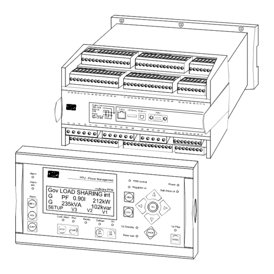
DEIF PPM Unit Hardware Overview
Unit Housing and PCB Slot Description
Details the unit's housing, PCB slots, and board positions.
Unit Top Side Terminal Layout
Provides an overview of the terminal connections on the unit's top side.
Diesel Generator Input/Output (I/O) Connections
DG Unit with PMS Processor I/Os
Illustrates I/O connections for DG units with PMS processor.
DG I/Os: Slots #3, #4, #7, and #8 Connections
Details I/O connections for DG units on slots #3, #4, #7, and #8.
Slot #1 Terminal Strip Description for DG
Describes terminals for Slot #1 (power supply and binary I/O) for DG.
Shaft Generator Input/Output (I/O) Connections
SG with Fixed Frequency Terminal Layouts
Illustrates I/O connections for SG units with fixed frequency.
SG I/Os: Slots #3, #4, #7, and #8 Connections
Details I/O connections for SG units on slots #3, #4, #7, and #8.
Slot #1 Terminal Strip Description for SG
Describes terminals for Slot #1 (power supply and binary I/O) for SG.
Bus Tie Breaker Input/Output (I/O) Connections
Bus Tie Between DG and SG Terminal Layouts
Illustrates I/O connections for bus tie breakers between DG and SG.
Bus Tie I/Os: Slots #3, #4, #7, and #8 Connections
Details I/O connections for bus tie units on slots #3, #4, #7, and #8.
Slot #1 Terminal Strip Description for Bus Tie
Describes terminals for Slot #1 (power supply and binary I/O) for Bus Tie.
Additional Operator Panel (AOP-2) Installation and Configuration
Display CANbus Cable Connection
Shows how to connect the display unit via CANbus.
CAN ID Configuration on AOP-2
Explains how to change the CAN ID for the AOP-2.
CAN ID Configuration on Display Unit
Explains how to change the CAN ID for the main display unit.
Detailed Wiring Diagrams and System Options
3-Phase AC Power Wiring
Shows the wiring diagram for 3-phase AC connections to the busbar and generator.
Communication Wiring (CANbus & Modbus)
Covers internal CANbus and Modbus RTU wiring configurations.
Load Sharing and Governor/AVR Control Wiring
Details wiring for load sharing, speed governor, and AVR control.
Binary and Analogue I/O Wiring
Explains wiring for binary inputs, wire break supervision, and analogue I/O.
Technical Specifications and Physical Data
DEIF PPM Technical Data
Lists electrical ratings, environmental conditions, safety, and EMC standards.
Unit Dimensions and Mounting
Provides unit physical dimensions and mounting recommendations.
Panel Cutout Specifications
Specifies the required panel cutout dimensions for installation.
Need help?
Do you have a question about the PPM and is the answer not in the manual?
Questions and answers