Table of Contents
Advertisement
SERVICE MANUAL
Ver. 1.3 2014.03
• STR-KM2 is the receiver section in HT-M2.
• STR-KM3 is the receiver section in HT-M3.
This receiver incorporates Dolby* Digital and Pro Logic Surround and the DTS** Digital Surround System.
* Manufactured under license from Dolby Laboratories. Dolby, Pro Logic, and the double- D symbol are trademarks of Dolby Laboratories.
** Manufactured under license under U.S. Patent Nos: 5,956,674; 5,974,380; 6,226,616; 6,487,535 & other U.S. and worldwide patents issued & pending.
DTS, the Symbol, & DTS and the Symbol together are registered trademarks & DTS Digital Surround | 96/24 is a trademark of DTS, Inc. Product
includes software. © DTS, Inc. All Rights Reserved.
This receiver incorporates High-Defi nition Multimedia Interface (HDMI
HDMI, the HDMI Logo, and High-Defi nition Multimedia Interface are trademarks or registered trademarks of HDMI Licensing LLC in the United States
and other countries.
"x.v.Color (x.v.Colour)" and "x.v.Color (x.v.Colour)" logo are trademarks of Sony Corporation.
"BRAVIA" is a trademark of Sony Corporation.
"PlayStation" is a registered trademark of Sony Computer Entertainment Inc.
MPEG Layer-3 audio coding technology and patents licensed from Fraunhofer IIS and Thomson.
"WALKMAN" is a registered trademark of Sony Corporation.
MICROVAULT is a trademark of Sony Corporation.
Windows Media is either a registered trademark or trademark of Microsoft Corporation in the United States and/or other countries.
This product contains technology subject to certain intellectual property rights of Microsoft. Use or distribution of this technology outside of this product is
prohibited without the appropriate license(s) from Microsoft.
Amplifi er section
Power Output
E51 and AR models
Stereo mode output (rated) (6 ohms, 1 kHz, THD 1%)
104 W + 104 W
Surround mode output
2)
(reference) (6 ohms,
1 kHz, THD 30%)
RMS output
FRONT:
220 W per channel
1)
CENTER:
220 W
(STR-KM3)
SURROUND:
220 W per channel
2)
Surround mode
(reference) (6 ohms, 100 Hz,
THD 30%)
SUBWOOFER:
220 W per channel
Other models
Stereo mode output (rated) (6 ohms, 1 kHz, THD 1%)
104 W + 104 W
2)
Surround mode output
(reference) (6 ohms,
1 kHz, THD 10%)
RMS output
FRONT:
170 W per channel
(STR-KM3)
165 W per channel
(STR-KM2)
1)
CENTER:
170 W
(STR-KM3)
9-890-591-04
Sony Corporation
2014C80-1
©
2014.03
Published by Sony EMCS (Malaysia) PG Tec
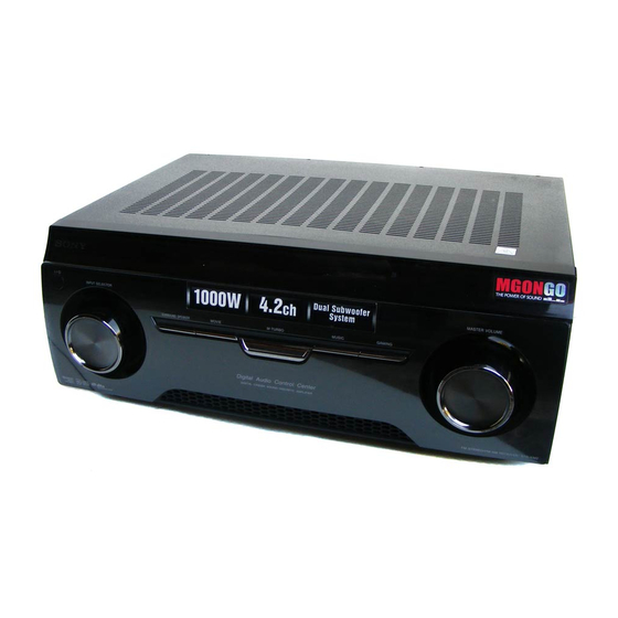
STR-KM2/KM3
Photo: STR-KM3
TM
) technology.
SPECIFICATIONS
SURROUND:
1)
Surround mode
2)
(reference) (6 ohms, 100 Hz,
THD 10%)
SUBWOOFER:
1)
1)
1)
Measured under the following conditions:
Area
Power requirements
1)
SAF, E51, SP
240 V AC, 50 Hz
MX
127 V AC, 60 Hz
AR, TH, AUS, RU 230 V AC, 50 Hz
1)
EA
127 V AC, 50 Hz
2)
Reference power output for front, center,
surround speakers and subwoofers. Depending
1)
on the sound fi eld settings and the source,
there may be no sound output.
1)
Saudi Arabia Model
170 W per channel
1)
Inputs
(STR-KM3)
Analog
165 W per channel
1)
(STR-KM2)
Digital (Coaxial)
Outputs (Analog)
1)
175 W per channel
AUDIO OUT
(STR-KM3)
1)
Tone
170 W per channel
(STR-KM2)
Gain levels
Reproduction frequency range:
FM tuner section
Tuning range
Antenna (aerial)
Antenna (aerial) terminals
MULTI CHANNEL AV RECEIVER
Russian Model
Australian Model
Mexican Model
Singapore Model
Thai Model
STR-KM3
E Model
STR-KM2/KM3
Sensitivity: 800 mV/
50 kilohms
Impedance: 75 ohms
Voltage: 800 mV/
1 kilohm
±6 dB, 1 dB step
28 Hz – 20,000 Hz
87.5 MHz – 108.0 MHz
FM wire antenna (aerial)
75 ohms, unbalanced
– Continued on next page –
Advertisement
Table of Contents

Related Manuals for Sony STR-KM3


Summarization of Contents
Servicing Notes
Model Identification
Identification of different model versions and their corresponding part numbers.
Component Replacement Notes
Notes on chip component, special component, and specific IC replacement procedures.
Unleaded Solder Information
Information about using and characteristics of unleaded solder, including lead-free marks.
Disassembly
Disassembly Flow
Step-by-step flow chart illustrating the disassembly procedure of the set.
Case Disassembly
Instructions and diagram for disassembling the main case of the unit.
Front Panel Section
Detailed steps and diagram for removing the front panel assembly.
Back Panel Section
Detailed steps and diagram for removing the back panel assembly.
Main Block and Board Removal
Instructions for removing the main block and main/thermal boards from the unit.
Test Mode
FL Check Mode
Test mode to check all fluorescent segments of the display for functionality.
Software Version Display Mode
Mode to display software versions of various components like microprocessor, DSP, sound tuning, and tuner.
SPDIF Update Mode
Procedure to update firmware using a CD player and the SPDIF input.
Preset Clear Modes
Modes to clear sound field or all preset contents, used after repair.
Electrical Check
FM Auto Stop Check
Procedure to check FM auto stop function using a signal generator and auto scanning.
Diagrams
Block Diagrams
Block diagrams illustrating signal flow for TUNER/AUDIO, DIGITAL, HDMI, KEY/DISPLAY/USB, and POWER KEY sections.
Printed Wiring Boards
Physical layout of components for DIGITAL AUDIO, MAIN, HDMI RE, POWER AVIDEO, DISPLAY, DCDC, LED BAR, USB, TUNER1 boards.
Schematic Diagrams
Detailed schematics for DIGITAL AUDIO, MAIN, HDMI RE, POWER AVIDEO, DISPLAY, DCDC, LED BAR, USB, TUNER1 boards.
IC Block Diagrams
Block diagrams showing internal structure of various ICs used in the unit.
Exploded Views
Case Section
Exploded view showing the case and related parts for disassembly.
Front Panel Section
Exploded view of the front panel assembly and its components.
Back Panel Section
Exploded view of the back panel assembly and its components.
Chassis Section
Exploded view of the chassis and major assemblies like transformers.
Heatsink Section
Exploded view of the heatsink assembly and associated transistors.
Electrical Parts List
Capacitors
List of capacitors with part numbers, descriptions, and specifications.
Coils
List of coils with part numbers, descriptions, and specifications.
Resistors
List of resistors with part numbers, descriptions, and specifications.
Connectors
List of connectors with part numbers and descriptions.
Diodes
List of diodes with part numbers and descriptions.
Ferrite Beads
List of ferrite beads with part numbers and descriptions.
ICs
List of Integrated Circuits with part numbers and descriptions.
Transistors
List of transistors with part numbers and descriptions.
Need help?
Do you have a question about the STR-KM3 and is the answer not in the manual?
Questions and answers