Advertisement
ONLINE PRODUCT REGISTRATION: Register your MSD product online. Registering your
product will help if there is ever a warranty issue with your product and helps the MSD R&D
team create new products that you ask for! Go to www.msdperformance.com/registration.
Note:
Solid Core spark plug wires cannot be used with an MSD Ignition.
Note:
An MSD cannot be used on vehicles with CD ignitions or distributorless ignition systems.
Parts Included:
1 - MSD 7AL-2 Plus Ignition
1 - Mag Pickup Extension Harness, PN 8860
1 - Mag Pickup Adapter Harness, PN 8859
1 - Coil Harness, PN 8863
WARNING: Before installing the MSD Distributor, disconnect the battery cables. When disconnecting
the battery cables, always remove the Negative (-) cable first and install it last.
FEATURES
RPM LIMITERS
The 7AL-2 Plus Ignition is equipped with a 2-step rev control. The Ignition will accept two rpm
modules so two different rev limits can be set. One rev limit can be used for overrev protection while
the second limit can be activated on the starting line for a lower rpm limit to assist in staging and
for consistent holeshots. When 12 volts are applied to the 2-step terminal (2'S'), Module 1 is active.
Module 2 is active when there is no 12 volts.
CYLINDER SELECT
This ignition can be used on 2, 4, 6 (even-fire) or 8-cylinder engines. The ignition is set for 8-cylinder
operation. To program the unit for other engines, remove the one screw that holds the cover to reveal
three wire loops (Figure 1). Cutting a wire loop determines the cylinder selection.
SPARK LED
When the coil fires, current is sensed and this
LED will flash. This confirms that the ignition
has received a trigger signal and that the coil
and ignition are working properly. (If the coil is
not connected, the LED will not flash.) When the
engine is running, it will appear solid.
M S D
•
W W W . M S D P E R F O R M A N C E . C O M
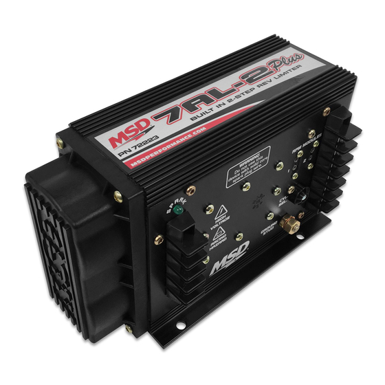
MSD 7AL-2 Plus Ignition
PN 7222/72223
1 - White Wire
1 - Red Wire
4 - Vibration Mounts and Hardware
4 - RPM Modules: 3K, 7K, 8K and 9K
Cylinders Loops to Cut
8
None
6
One
4
Two
2
Three
Figure 1 Cylinder Programming.
•
( 9 1 5 )
8 5 7 - 5 2 0 0
Remove cap
Cut loops
•
F A X
( 9 1 5 )
8 5 7 - 3 3 4 4
Advertisement
Table of Contents

Related Manuals for MSD 72223


Summarization of Contents
Features
RPM Limiters
The 7AL-2 Plus Ignition has a 2-step rev control with two RPM modules for different rev limits.
Cylinder Select
Program the unit for 2, 4, 6, or 8-cylinder engines by cutting wire loops.
Spark LED Indicator
The LED flashes when the coil fires, indicating proper operation, and appears solid when running.
General Information
Battery Requirements
Operates on negative ground 12V systems, withstands 24V jump starts, and requires 5V minimum.
Recommended Coils
Can be used with stock or aftermarket coils; Pro Power Coil recommended for short duration racing.
Tachometer Output
Provides a 12V square wave signal for tachometers and other RPM devices.
Spark Plugs and Wires
Requires helically wound wires and proper routing to minimize EMI. Solid core wires are not usable.
Miscellaneous Information
Sealing Information
Do not seal the MSD unit; it has conformal coating and needs drainage for moisture.
Welding Precautions
Disconnect heavy power cables and tach ground wire when welding to prevent damage.
Distributor Cap and Rotor
Recommended to install new cap/rotor. Drill vent holes in cap for crossfire prevention.
Initial Spark Phenomenon
Momentary spark on key-on or battery connection is normal due to capacitor charging.
Wiring Guide
General Wiring Information
Shorten wires with quality connectors or solder. Use larger gauge wire for extensions.
Ground Connections
Connect grounds to battery negative, engine block, or chassis. Ensure clean, paint-free surface.
Ballast Resistor Bypass
Bypass is not necessary; MSD receives main power directly from the battery.
Noise Capacitor
MSD offers a Noise Capacitor/Filter to help eliminate EMI noise.
Terminal Connections Overview
Details wiring connections for Coil, Battery, Tach, 2-Step, Ignition, Points, and Magnetic Pickup.
Inoperative Tachometers
Tachometer Compatibility List
Lists common aftermarket tachometers and their compatibility with MSD White Wire or Magnetic Trigger.
Misses and Intermittent Problems
Inspection Points for Performance Issues
Inspect plug wires, coil primary connections, battery charge, and wiring for corrosion.
LED Troubleshooting Indicator
The LED indicates primary coil current. No flash means no current; check connections, coil, or ignition.
Checking for Spark
Spark Check - White Wire Trigger
Tap White wire to ground to check for spark. If no spark, proceed to step 6.
Spark Check - Magnetic Pickup Trigger
Short Green and Violet wires together to check for spark. If no spark, proceed to step 6.
Troubleshooting No Spark Conditions
Inspect wiring, substitute coil, check 12V supply, or send unit for repair if no spark persists.
GM Large Cap HEI Distributor Types
HEI 5-Pin Distributor Hesitation
For 5-pin HEI models with hesitation/stall, contact MSD for a bolt-in diode.
HEI Distributor Rotor Button
Stock rotor button must be replaced with an MSD Low Restraint Bushing, PN 8412.
Service and Warranty Information
Warranty Service Procedure
Return components for repair with RMA number, proof of purchase, and detailed problem description.
Limited Warranty Terms
One-year warranty against defects in material/workmanship for intended normal use. Repair or replacement provided.
Need help?
Do you have a question about the 72223 and is the answer not in the manual?
Questions and answers