
Related Manuals for MAXTHERMO MC-2538


Summarization of Contents
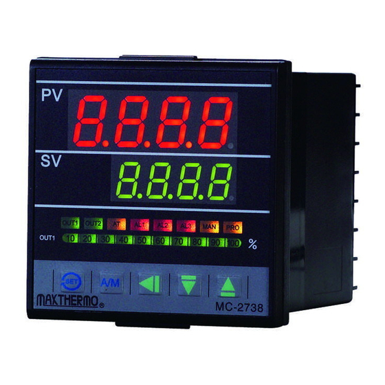
Panel Function Overview
Display Indicators (PV, SV)
Shows Process Value (PV) and Set Value (SV) on the controller display.
Control and Mode Keys
Buttons for setting, manual/auto switching, and navigation (SET, A/M, Shift, Down, Up).
Status and Alarm Indicators
LEDs indicating output status, auto-tuning, and alarms (OUT1, OUT2, AT, AL1-3, MAN, PRO).
Controller Operation Flow
User Level Operation
Navigating and setting parameters in the primary user interface level.
PID Level Operation
Accessing and configuring PID control parameters for advanced tuning.
Input Configuration Level
Main Input Selections
Configuring primary input types, decimal points, and setpoint limits.
Alarm Mode and Timing Settings
Setting alarm modes, delays, and hysteresis for alarms AL1, AL2, AL3.
Advanced Set Level Configuration
Parameter Display and Function Settings
Customizing parameter display and configuring core functions via digital settings.
Program Control Setup
Program Pattern and Segment Configuration
Setting up program patterns, segments, and timers for automated control sequences.
Special Function Configuration
Dual Output Functionality
Configures output 1 for heating and output 2 for cooling.
Loop Broken Alarm Configuration
Enables alarms for loop short or open conditions, requiring specific parameter settings.
Program Control Setup
Guides setting up programs with ramp/soak segments and specific timing.
Technical Specifications
Input and Output Specifications
Details supported input types (T/C, DCV, DCmA) and output options (Relay, SSR, Current, Motor Valve).
Control Modes and Electrical Characteristics
Describes control modes (ON/OFF, P, I, D) and electrical properties like voltage and power.
Mechanical Characteristics and Weight
Provides physical specifications including operating temperature, humidity, and device weight.
Troubleshooting: Error Codes
Sensor and Communication Errors
Lists codes for sensor open circuits, A/D converter, and interface failures.
PV/SV and RAM Errors
Details error codes related to PV/SV limits, sub-control signals, and RAM failures.
Input Signal Selection Guide
Thermocouple and RTD Input Types
Maps thermocouple and RTD types to their corresponding codes and ranges.
Voltage, Current, and Special Input Types
Lists available voltage, current, and special inputs with their codes and ranges.
Alarm Function Selection
Deviation and Absolute Value Alarms
Configures deviation and absolute value alarms with inhibit options.
Program and System Error Alarms
Sets up program segment alarms, run alarms, and system error alerts.
Hookup Diagrams (MC-2438)
Power Supply and Control Output Connections
Wiring for power input and control outputs (Relay, SSR, mA, V).
Input, Alarm, and Communication Wiring
Diagrams for input signals, alarm outputs, retransmission, communication, and remote SV.
Hookup Diagrams (MC-2738)
Power Supply and Control Output Wiring
Wiring for power input and control outputs (Relay, SSR, mA, V) for MC-2738.
Input, Alarm, and Communication Wiring
Diagrams for input signals, alarm outputs, retransmission, communication, and remote SV for MC-2738.
Hookup Diagrams (MC-2538/MC-2638)
Power Supply and Control Output Wiring
Wiring for power input and control outputs (Relay, SSR, mA, V) for MC-2538/MC-2638.
Input, Alarm, and Communication Wiring
Diagrams for input signals, alarm outputs, retransmission, communication, and remote SV for MC-2538/MC-2638.
Hookup Diagrams (MC-2838)
Power Supply and Control Output Wiring
Wiring for power input and control outputs (Relay, SSR, mA, V) for MC-2838.
Input, Alarm, and Communication Wiring
Diagrams for input signals, alarm outputs, retransmission, communication, and remote SV for MC-2838.
Alarm Action Descriptions
Deviation and Absolute Value Alarm Actions
Explains behavior for deviation, absolute value, band, and inhibit alarms.
Program and System Alarm Actions
Describes actions for program segment, run alarms, system errors, ramp, and soak alarms.
Product Ordering Information
Model Number and Output Options
Details model identification, output modes for heating/cooling, and alarm configurations.
Transmitter, Input, and Communication Options
Lists available transmitter outputs, second input types, and communication protocols.
Function Availability Matrix
Core Function Support (OUT2, ALM2, ALM3)
Indicates availability of OUT2, ALM2, ALM3 functions across MC-2X38 models.
Advanced Function Support (R-SV, TRS, RS485, Master/Slave)
Shows support for R-SV, TRS, RS485, and Master/Slave communication for different models.
Need help?
Do you have a question about the MC-2538 and is the answer not in the manual?
Questions and answers