Table of Contents
Advertisement
Advertisement
Table of Contents

Summarization of Contents
CABINET COOLING GUIDE
INTAKE AND EXHAUST
Balance static pressures using intake and exhaust variables like fans or vents.
FAN POSITIONING
Position fans at the top for exhaust and bottom for intake, leveraging natural convection.
CFM REQUIREMENTS
Calculate required CFM by dividing cabinet volume by 1728 and multiplying by three.
KEY FEATURES
ALUMINIUM FRAME
Features an aluminum frame with CNC machined corners for a professional appearance.
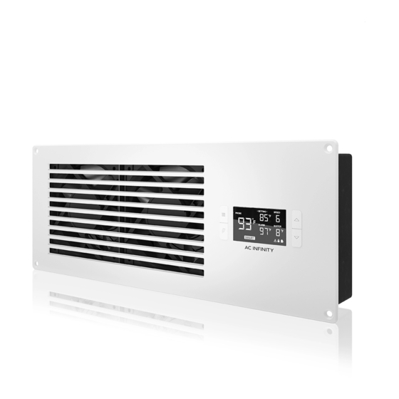
SMART CONTROLLER
Manages temperature, speed, alarms, and energy modes for optimal performance.
DETACHABLE FILTER
High-density filter removes dust and is easily detached for cleaning.
DUAL BALL BEARINGS
Long-life ball bearings (67,000 hours) allow mounting fans in any direction.
THERMAL PROBE
Stainless steel corded sensor probe ensures accurate temperature readings.
FAN EXPANSION PORTS
Ports enable connecting additional fan units to share controls and power.
INSTALLATION STEPS 1-2
STEP 1: MOUNTING AND STENCIL
Determine mounting location and position stencils, applying tape to outer edges.
STEP 2: OUTLINE MARKINGS
Use a pencil to outline the center square and screw holes on the stencil.
INSTALLATION STEPS 3-4
STEP 3: DRILL SCREW HOLES
Drill four screw holes, using a 16/64" bit for machine screws.
STEP 4: CUT CENTER PIECE
Cut out the center piece using a saw, drilling corners first if needed.
INSTALLATION STEPS 5-6
STEP 5: PLACE FAN UNIT
Align the fan unit in the cut square, ensuring clearance for the backside.
STEP 6: SECURE FAN UNIT
Secure the fan unit frame using machine or wood screws and nuts.
INSTALLATION STEPS 7-8
STEP 7: INSERT FILTER PIECE
Align and insert the filter piece into the docking holes on the fan unit's backside.
STEP 8: SECURE FILTER PIECE
Push the filter piece against the fan unit back to click it into position.
INSTALLATION STEPS 9-10
STEP 9: CONNECT POWER ADAPTER
Plug the adapter's connector into the "POWER" port on the fan unit backside.
STEP 10: CONNECT TO OUTLET
Plug the adapter head into an outlet and check if the screen is on.
INSTALLATION STEPS 11-12
STEP 11: CONNECT THERMAL PROBE
Plug the probe's connector into the "PROBE" port on the fan unit backside.
STEP 12: POSITION THERMAL PROBE
Position the thermal probe near devices with the highest temperatures.
FILTER MAINTENANCE STEPS 1-2
STEP 1: DETACH FILTER
Pull the filter's lever to release it from the fan unit backside for cleaning.
STEP 2: RINSE FILTER
Rinse the filter with running water or wipe with a damp cloth to remove dust.
FILTER MAINTENANCE STEPS 3-4
STEP 3: DRY FILTER
Wipe down the filter thoroughly with a cloth and ensure it's dry before reattaching.
STEP 4: REATTACH FILTER
Push the filter piece against the fan unit back to put it into position.
CONNECTING MORE FANS
FAN EXTENSIONS EXPLAINED
S-series units connected to T-series share fan speed and temperature trigger settings.
PROGRAMMING OVERVIEW
MODE BUTTON FUNCTION
Cycles through modes (AUTO, SMART, SPEED, ALARM, BUFFER) and locks/unlocks display.
UP/DOWN BUTTON FUNCTION
Adjusts setting temp, alarm temp, brightness, or fan speed.
LEAF BUTTON FUNCTION
Turns display off for eco mode or changes temperature units (°F/°C).
SETTING TEMP DISPLAY
Shows the temperature set for fans to trigger in AUTO and SMART modes.
ALARM TEMP DISPLAY
Shows the temperature set for the fan alarm system to trigger.
PROBE TEMP DISPLAY
Actively shows the current temperature measured by the thermal probe.
FAN SPEED DISPLAY
Shows the current fan speed; six speeds are available.
BUFFER SETTING DISPLAY
Displays buffer range settings for AUTO and SMART mode programming.
ALERT ICONS SUMMARY
Indicate fan failure, alarm, or display lock status.
PROGRAMMING MODES
QUICK START GUIDE
Operate in AUTO mode like a thermostat by setting temperature triggers.
SPEED SETTING MODE
Fans run non-stop; speed adjusted via UP/DOWN buttons.
AUTO MODE EXPLANATION
Fans start when PROBE temp exceeds SETTING temp; stop when it drops below with a buffer.
PROGRAMMING SETTINGS
BUFFER SETTING DETAILS
Buffer prevents rapid fan cycling; range can be adjusted for SMART mode.
SMART MODE FUNCTION
Fans change speed based on temperature; speed decreases as PROBE temp drops below SETTING.
ALARM SETTING
SETTING ALARM TRIGGER
Set alarm temperature; alarm activates when PROBE temp reaches or exceeds it.
ALARM BEHAVIOR
Fans run at max speed with beeps until temp drops or buttons are pressed.
DISPLAY AND CONTROL OPTIONS
FAHRENHEIT OR CELSIUS SCALE
Set temperature display to Fahrenheit or Celsius by holding the LEAF button.
DISPLAY BRIGHTNESS ADJUSTMENT
Adjust display brightness using MODE button combined with UP/DOWN buttons.
CONTROLLER LOCK FUNCTION
Lock the controller by holding MODE button to prevent accidental changes.
ECO-DISPLAY MODE
Conserve energy by turning off the display; programs run in the background.
ALERT ICONS EXPLAINED
FAN FAILURE ALERT ICON
Indicates one or more fans in the system have failed.
DISPLAY LOCK ALERT ICON
Flashes when buttons are pressed while the controller is locked.
ALARM ALERT ICON
Flashes when PROBE temperature reaches or exceeds the set alarm temperature.
AC INFINITY PRODUCTS
AIRCOM SERIES OVERVIEW
Component fan systems for receivers, amplifiers, and AV components.
CLOUDPLATE SERIES OVERVIEW
Rack fan systems for cooling audio video, home theater, and IT equipment racks.
WARRANTY INFORMATION
PRODUCT WARRANTY COVERAGE
Two-year warranty against manufacturing defects, covering material or workmanship issues.
WARRANTY EXCLUSIONS
Does not cover abuse, misuse, physical damage, water submersion, or incorrect installation.
SATISFACTION GUARANTEE
Offers replacement or full refund if not 100% satisfied with the product.


Need help?
Do you have a question about the AIRFRAME T9 and is the answer not in the manual?
Questions and answers