Table of Contents
Advertisement
SARA-G3 and SARA-U2 series
GSM/GPRS and GSM/EGPRS/HSPA
Cellular Modules
System Integration Manual
Abstract
This document describes the features and the system integration of
the SARA-G3 series GSM/GPRS cellular modules and the SARA-U2
GSM/EGPRS/HSPA cellular modules.
These modules are complete and cost efficient solutions offering
voice and/or data communication over diverse cellular radio access
technologies in the same compact SARA form factor: the SARA-G3
series support up to four GSM/GPRS bands, while the SARA-U2
series support up to five high-speed HSPA bands and up to four
GSM/EGPRS bands.
www.u-blox.com
UBX-13000995 - R26
Advertisement
Table of Contents

Related Manuals for Ublox SARA-U270 ATEX


Summarization of Contents
Preface
u-blox Technical Documentation
Overview of u-blox's technical documentation resources for cellular modules.
How to use this Manual
Guidance on navigating and utilizing the System Integration Manual structure and symbols.
Questions
Information on how to get support and ask questions about u-blox cellular integration.
Technical Support
Details on accessing worldwide web and email technical support for u-blox products.
1 System description
1.1 Overview
Introduction to SARA-G3 and SARA-U2 series modules, their form factor, and capabilities.
1.2 Architecture
Description of the internal block diagrams and main sections of SARA modules.
1.3 Pin-out
Detailed listing of module pins, their functions, I/O, and descriptions.
1.4 Operating modes
Explanation of the different operating modes of SARA modules and their transitions.
1.5 Supply interfaces
Information on power supply interfaces including VCC, V_BCKP, and V_INT.
1.6 System function interfaces
Details on module power-on, power-off, reset, and clock signal interfaces.
1.7 Antenna interface
Guidelines and requirements for the ANT and ANT_DET pins for RF connection and detection.
1.8 SIM interface
Description of the SIM interface, voltage support, and SIM card detection functionality.
1.9 Serial interfaces
Details on UART, auxiliary UART, USB, and DDC (I2C) serial interfaces.
1.10 Audio interface
Guidelines for analog and digital audio interfaces, including voice-band processing.
1.11 General Purpose Input/Output (GPIO)
Configuration and usage of GPIO pins for various functions like network status and GNSS control.
1.12 Reserved pins (RSVD)
Information about reserved pins and their connection requirements, specifically pin 33 to GND.
1.13 System features
Overview of various system features including network, antenna, jamming, and power saving.
2 Design-in
2.1 Overview
General guidelines for optimal integration of SARA modules in the final application board design.
2.2 Supply interfaces
Guidelines for designing VCC, V_BCKP, and V_INT supply interfaces for SARA modules.
2.3 System functions interfaces
Guidelines for implementing power-on, reset, and 32 kHz signal interfaces for SARA modules.
2.4 Antenna interface
Guidelines for antenna selection, RF interface design, and detection circuit.
2.5 SIM interface
Guidelines for SIM card circuit design, including connectors, chips, and layout considerations.
2.6 Serial interfaces
Guidelines for designing UART, auxiliary UART, USB, and DDC (I2C) serial interfaces.
2.7 Audio interface
Guidelines for analog and digital audio interfaces, including microphone, speaker, and codec connections.
2.8 General Purpose Input/Output (GPIO)
Guidelines for GPIO circuit and layout design for various module functions.
2.9 Reserved pins (RSVD)
Information about reserved pins and their connection requirements, specifically pin 33 to GND.
2.10 Module placement
Guidelines for optimal module placement considering RF line length, EMI, and heat dissipation.
2.11 Module footprint and paste mask
Suggested footprint and paste mask layout for SARA modules, including dimensions.
2.12 Thermal guidelines
Guidelines and considerations for module thermal performance during operation and heat dissipation.
2.13 ESD guidelines
ESD immunity test overview, reference design tests, and application circuits for protection.
2.14 SARA-G3 / SARA-U2 ATEX modules integration in devices intended for use in potentially explosive atmospheres
General guidelines and specific circuit design considerations for ATEX modules in explosive atmospheres.
2.15 Schematic for SARA-G3 and SARA-U2 series module integration
Example schematic diagrams for integrating SARA-G3 and SARA-U2 modules into an application board.
2.16 Design-in checklist
Checklists for validating the schematic, layout, and antenna design for SARA modules.
3 Handling and soldering
3.1 Packaging, shipping, storage and moisture preconditioning
Information on packaging, shipping, storage, and moisture preconditioning for SARA modules.
3.2 Handling
Guidelines for handling ESD-sensitive SARA modules, including EPA and safety practices.
3.3 Soldering
Recommendations for soldering SARA modules, including paste, reflow profiles, and inspection.
4 Approvals
4.1 Product certification approval overview
Overview of product certification approval processes and categories for SARA modules.
4.2 US Federal Communications Commission notice
FCC ID and notices for SARA modules, including safety warnings and declaration of conformity.
4.3 Innovation, Science and Economic Development Canada notice
ISED Canada certification numbers and notices, including RF exposure information.
4.4 European conformance CE mark
Compliance of SARA modules with European Radio Equipment Directive and related standards.
4.5 Brazilian Anatel certification
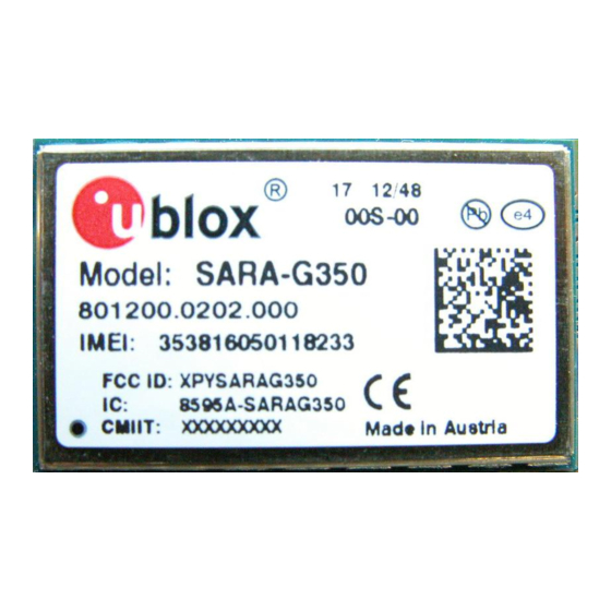
Anatel certification numbers for SARA-G310, SARA-G350, and SARA-U201 modules.
4.6 Australian Regulatory Compliance Mark
Compliance of SARA modules with Australian telecommunications standards.
4.7 Mexican IFT certification
IFT certification number for the SARA-U260 module.
4.8 Chinese CCC mark
CCC mark certification for SARA-G340-02, SARA-G350, SARA-U201, and SARA-U270 modules.
4.9 Korean KCC certification
KCC ID for SARA-U270 modules.
4.10 Taiwanese NCC certification
NCC IDs for SARA-G340-02, SARA-G350, SARA-U201, and SARA-U270 modules.
4.11 Japanese Giteki certification
Giteki certification details for SARA-U201 modules.
4.12 SARA-G3 / SARA-U2 ATEX modules conformance for use in explosive atmospheres
Conformance of ATEX modules for use in potentially explosive atmospheres according to standards.
5 Product testing
5.1 u-blox in-series production test
Description of automatic in-series production tests performed by u-blox for quality assurance.
5.2 Test parameters for OEM manufacturers
Key tests and verification points for OEM manufacturers during device integration.
A Migration between LISA and SARA-G3 modules
A.1 Overview
Overview of the migration procedure from LISA to SARA-G3 modules, highlighting commonalities.
A.2 Checklist for migration
Checklist to assist in choosing the optimal SARA-G3 module and verifying hardware requirements.
A.3 Software migration
Guidance on migrating software between SARA-G3 and LISA modules, considering firmware differences.
A.4 Hardware migration
Comparison of hardware differences in interfaces between SARA-G3 and LISA modules.
B Migration between SARA-G3 and SARA-U2
B.1 Overview
Overview of migrating between SARA-G3 and SARA-U2 modules, emphasizing form factor and pin compatibility.
B.2 Pin-out comparison between SARA-G3 and SARA-U2
Table comparing pin definitions and electrical differences between SARA-G3 and SARA-U2 modules.
B.3 Schematic for SARA-G3 and SARA-U2 integration
Example schematic diagram for integrating SARA-G3 and SARA-U2 modules on the same application board.
Need help?
Do you have a question about the SARA-U270 ATEX and is the answer not in the manual?
Questions and answers