
Related Manuals for Rosemount 3493


Summary of Contents for Rosemount 3493
- Page 1 Reference Manual 00809-0100-4841, Rev. AA May 2007 Rosemount 3490 Series Universal Control Unit www.rosemount.com...
- Page 3 Within the United States, Rosemount Inc. has two toll-free assistance numbers. Customer Central: 1-800-999-9307(7:00 a.m. to 7:00 p.m. CST) Technical support, quoting, and order-related questions.
-
Page 5: Table Of Contents
Switching on ..........4-2 Switching on the 3491/3493 ......4-2 Switching-on the 3492 . - Page 6 About Alarms ........4-59 About Totalising On Model 3491 ......4-62 About Totalising on Model 3492 .
- Page 7 Reference Manual 000809-0100-4841, Rev. AA Rosemount 3490 Series May 2007 APPENDIX E Overview ..........E-1 ®...
- Page 8 Reference Manual 00809-0100-4841, Rev. AA Rosemount 3490 Series May 2007...
- Page 9 Explosions could result in death or serious injury. • Verify the operating environment of the Rosemount 3490 Series Control Unit is consistent with the appropriate locations certifications. Electrical shock could cause death or serious injury.
-
Page 10: Manual Overview
00809-0100-4841, Rev. AA Rosemount 3490 Series May 2007 MANUAL OVERVIEW This manual provides installation, configuration and maintenance information for the Rosemount 3490 Series Control Unit. Section 2: Overview Section 3: Installation Section 4: Getting Started Section 5: Service and Health Checks... -
Page 11: Service Support
To expedite the return process outside of the United States, contact the nearest Rosemount representative. Within the United States, call the Rosemount National Response Center using the 1-800-654-RSMT (7768) toll-free number. This center, available 24 hours a day, will assist you with any needed information or materials. - Page 12 Reference Manual 00809-0100-4841, Rev. AA Rosemount 3490 Series May 2007...
-
Page 13: Introduction To The 3490 Series
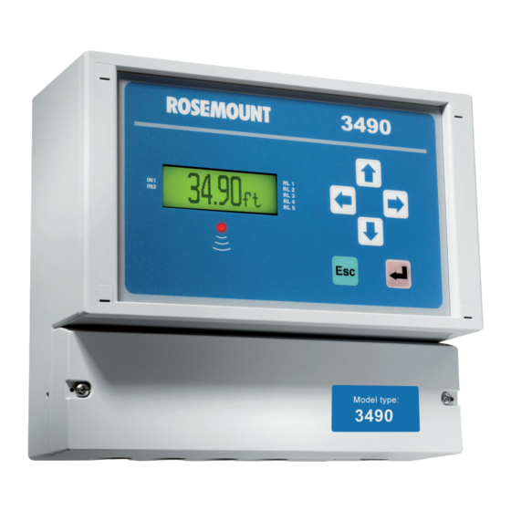
Control Unit Front Panel ......page 2-4 INTRODUCTION TO THE The Rosemount 3490 Series is a range of control units, providing a wide range of control functions and display of the measured variable. -
Page 14: Transmitter Input
Model 3492 will accept inputs from two HART transmitters. NOTE The Rosemount 3490 Series is designed for non-hazardous (safe) area installation, but can be connected to a transmitter installed in a hazardous area. For certifications of the Control Unit, see Appendix B. -
Page 15: Control Unit Functions
00809-0100-4841, Rev. AA Rosemount 3490 Series May 2007 CONTROL UNIT For a full guide to programming the Rosemount 3490 Series Control Unit, see “Programming” on page 4-9. FUNCTIONS Standard functions Using either the input from a 4-20mA or HART transmitter, all models of the... -
Page 16: Control Unit Front Panel
Reference Manual 00809-0100-4841, Rev. AA Rosemount 3490 Series May 2007 CONTROL UNIT This section describes the front panel fascia, which comprises keypad, display, and status LED. FRONT PANEL NOTE: A full specification for the control unit is in Appendix A. -
Page 17: Display
There are some display differences between the models: • On models 3491 and 3492, a bar graph represents the 4-20mA output signal. (Model 3493 display can be programmed to show the bar graph.) • On model 3492, there are extra graphics relating to having two transmitters connected to the control unit. -
Page 18: Status Led
Reference Manual 00809-0100-4841, Rev. AA Rosemount 3490 Series May 2007 Figure 2-5. Typical display of model 3493 HART Transmitter Relay (RL) status. communicating o = de-energized, = energized Totaliser 2 (Daily total) (Absent if idle) T = Totaliser Off-line/on-line status. -
Page 19: Safety Messages
High voltage that may be present on leads could cause electrical shock: Avoid contact with leads and terminals. Make sure the main power to the Rosemount 3490 Series is off, and the lines to any other external power source are disconnected or not powered while wiring. -
Page 20: Before You Install
00809-0100-4841, Rev. AA Rosemount 3490 Series May 2007 BEFORE YOU INSTALL The Rosemount 3490 Series Control Unit may be connected to a transmitter located in a hazardous area. The Control Unit must not itself be located in a hazardous area. General considerations •... -
Page 21: Mounting The Rosemount 3490 Series Control Unit
Reference Manual 00809-0100-4841, Rev. AA Rosemount 3490 Series May 2007 MOUNTING THE ROSEMOUNT 3490 SERIES CONTROL UNIT Mounting the IP-rated Guidelines: Wall Mount Models • This housing is rated IP65. It is suitable for mounting outside, but this should be above any flood level, away from any overflow path, and away from direct sunlight. -
Page 22: Mounting Panel Models
Reference Manual 00809-0100-4841, Rev. AA Rosemount 3490 Series May 2007 Mounting Panel Models Guidelines: • This housing is rated IP40 and is designed for panel mounting in a weatherproof environment. An optional fascia overlay hood is available which improves the IP rating to IP65. - Page 23 Reference Manual 00809-0100-4841, Rev. AA Rosemount 3490 Series May 2007 Figure 3-1. Screw clamp fitted Screw clamp frame Front panel bezel Screw clamp with threaded spindle...
-
Page 24: Electrical Installation
Reference Manual 00809-0100-4841, Rev. AA Rosemount 3490 Series May 2007 ELECTRICAL INSTALLATION Electrical Connections All field wiring connections are accessible by removing the lower terminal cover, which is secured by two screws on the IP-rated version, and by four on Wall Mount Models screws on the NEMA 4X rated version. - Page 25 Reference Manual 00809-0100-4841, Rev. AA Rosemount 3490 Series May 2007 Cable gland and conduit notes for NEMA4X-rated Wall Mount It is the responsibility of the user to ensure suitable cable glands or conduit connections are used when wiring to the 3490 Series Control Unit to maintain the enclosure integrity.
-
Page 26: Electrical Connections On Panel Mount Model
Reference Manual 00809-0100-4841, Rev. AA Rosemount 3490 Series May 2007 Electrical connections All connections are made to the rear of the control unit using the two part terminal connectors provided. on Panel Mount Model NOTE It is the responsibility of the installer to: •... -
Page 27: Transmitter Connections And Cabling
Reference Manual 00809-0100-4841, Rev. AA Rosemount 3490 Series May 2007 Terminal Function Layout I.S. Earth (Earth symbol) Negative Positive (1) Mains powered control unit only. (2) DC powered control unit only. Transmitter Connections Connection of a transmitter to the control unit does not confer Intrinsic Safety on the transmitter. -
Page 28: Connecting Hart Transmitters To 3492
The plug/socket connectors are polarized to prevent inter-changeability and incorrect connection Connecting HART Model 3492 of the Rosemount 3490 Series takes the input from two HART transmitters and will perform various calculations to create the sum, Transmitters to 3492 difference, or product of the two inputs. -
Page 29: Power Connections
Telematic Limited, are fitted if local conditions make this advisable. Earthing Connections The IP-rated Rosemount 3490 Series of Control Units are double insulated and DO NOT require a mains earth. DO NOT connect a mains earth to terminal 30. -
Page 30: Relay Connections
Reference Manual 00809-0100-4841, Rev. AA Rosemount 3490 Series May 2007 Relay Connections The 5 voltage-free contact relays are grouped in the following configuration: Table 3-3. Relay configuration groups 3490 Series Control Unit (Wall Mount) 3490 Series Control Unit (Panel Mount) -
Page 31: Rs232 Connections
Reference Manual 00809-0100-4841, Rev. AA Rosemount 3490 Series May 2007 RS232 Connections The RS232 connections, terminals 4-6, may be used for exchanging data with a PC or a handheld device. Model 3493 is supplied with a data-download socket. Connect the flying leads from the socket provided as follows: •... - Page 32 Reference Manual 00809-0100-4841, Rev. AA Rosemount 3490 Series May 2007 3-14...
-
Page 33: Safety Messages
Reference Manual 00809-0100-4841, Rev. AA Rosemount 3490 Series May 2007 Section 4 Getting started Safety messages ....... . . page 4-2 Switching on . -
Page 34: Switching On
Rosemount 3490 Series May 2007 SWITCHING ON Switching on the The Rosemount 3490 Series Control Unit takes the input from a HART transmitter or 4-20mA transmitter. 3491/3493 3491 and 3493 support level, content and flow measurements. 3493 software has data logging support. -
Page 35: Switching-On The 3492
May 2007 NOTE: If being used for the first time with a Rosemount 3100 Series transmitter, there will be a prompt for the Bottom Reference of the transmitter. This value will then be used to automatically set-up the transmitter 4-20mA output span over this range. -
Page 36: The Hierarchical Menu System
Reference Manual 00809-0100-4841, Rev. AA Rosemount 3490 Series May 2007 THE HIERARCHICAL MENU SYSTEM How to navigate the If you wish to have a quick tour of the menu system, follow instructions in this section, otherwise feel free to explore on your own. Should you get lost, use menu system the ESC button repeatedly until the primary display re-appears. - Page 37 Reference Manual 00809-0100-4841, Rev. AA Rosemount 3490 Series May 2007 Operating modes "On-line" and "off-line" affect outputs on the 3490 Series Control Unit (see section “Modes of operation“ on page 4-11). If the 3490 Series Control Unit is configured and outputs are connected up to equipment e.g.
-
Page 38: About Parameter Screens
Reference Manual 00809-0100-4841, Rev. AA Rosemount 3490 Series May 2007 11. Within the menus, there are also parameter screens for programming - setting-up for an application, adjusting default settings, etc. - and screens for displaying read-only information. Figure 4-7. Example of a parameter screen... - Page 39 Reference Manual 00809-0100-4841, Rev. AA Rosemount 3490 Series May 2007 6. Press the UP-ARROW button once to change the 5 to a 6. The UP-ARROW button will scroll up through the numbers. The DOWN-ARROW button will scroll down through the numbers.
-
Page 40: Programming
Reference Manual 00809-0100-4841, Rev. AA Rosemount 3490 Series May 2007 PROGRAMMING Before you begin Before embarking on programming (configuring) the 3490 Series Control Unit, it is recommended that you have a working knowledge of important features and programming philosophies. All setting up is achieved from the front panel of the 3490 Series Control Unit;... - Page 41 Reference Manual 00809-0100-4841, Rev. AA Rosemount 3490 Series May 2007 Figure 4-13. Navigating to the DIRECT menu Wizards Programming is best achieved through easy-to-follow Wizards. They are simply a sequence of on-screen prompts, allowing you to easily set-up an individual function or a large application without fuss.
- Page 42 Reference Manual 00809-0100-4841, Rev. AA Rosemount 3490 Series May 2007 Outputs: This includes setting-up: • 4-20mA Current Output (see Section “Current Output“ on page 4-39). • Relays (see “Relays“ on page 4-40). Other features: This includes configuring Data Logging, Alarm handling, the Primary Display, Serial Communications and Pin Security.
-
Page 43: Comfort (System) Settings
Reference Manual 00809-0100-4841, Rev. AA Rosemount 3490 Series May 2007 Comfort (system) Prior to setting up, it is advisable to check the settings of these parameters and, if necessary, make changes. This includes setting the time and date, settings switching off the keypad sound and changing language. -
Page 44: Transmitter Inputs
Section “Digital Inputs IN1 and IN2“ on page 4-34. On this page, follow the guidance for the particular model of the 3490 Series Control Unit that you have e.g. model 3491. You will be directed to the sections that are appropriate for your particular system. NOTE: If you want to edit or view parameters (e.g. - Page 45 Setting up Input Channel 1 for a 4-20mA input This section is applicable if a transmitter with a 4-20mA output is connected. Models 3491 and 3493 support the connection of a single 4-20mA transmitter Do not connect a second 4-20mA transmitter.
- Page 46 Reference Manual 00809-0100-4841, Rev. AA Rosemount 3490 Series May 2007 Table 4-3. P117 Options P117 Channel 1 Output Action +ve value Drop immediately to zero. None Continue measuring. Hold output at zero. -ve value Rise immediately to zero. This feature is particularly useful in an Open Channel Flow application (OCF) where a small standing or remaining liquid level in the channel would cause continued totalising of flow when no actual flow exists.
- Page 47 Reference Manual 00809-0100-4841, Rev. AA Rosemount 3490 Series May 2007 P117 Channel 1 Low Cut-off Use for forcing D800 to zero while D851 is less than P117 P20x Displayed measurement units P200 for PV (D800), P201 for SV (D801) and P202 for TV (D802)
- Page 48 Reference Manual 00809-0100-4841, Rev. AA Rosemount 3490 Series May 2007 Setting up Input Channel 2 for a 4-20mA input (model 3492 only) Model 3492 supports the connection of a single 4-20mA transmitter. Do not connect a second 4-20mA transmitter. This section is applicable if a transmitter with a 4-20mA output is connected and supplying the same analog measurements to both input channels;...
- Page 49 Reference Manual 00809-0100-4841, Rev. AA Rosemount 3490 Series May 2007 P127 is a low cut-off parameter that allows the user to force the channel 2 output (D852) to be zero when the calculated value falls below a user defined value: Table 4-4.
- Page 50 Reference Manual 00809-0100-4841, Rev. AA Rosemount 3490 Series May 2007 P124 Channel 2 Scaling Factor This is for scaling the D802 value into required units (P200). If PV value is the liquid level, set P124 to the level measurement represented by the 20mA output from transmitter.
- Page 51 Reference Manual 00809-0100-4841, Rev. AA Rosemount 3490 Series May 2007 Setting up Input Channel 1 for a HART input This section is applicable if a HART transmitter is connected. NOTE: The "Duty" Wizard is recommended for configuring an application. Menu: SETUP / [CONTROL UNIT /] DUTY(Mode) / Duty Wizard The HART transmitter digitally communicates pre-calculated values of the four variables (PV, SV, TV and FV) to the 3490 Series Control Unit.
- Page 52 Reference Manual 00809-0100-4841, Rev. AA Rosemount 3490 Series May 2007 Figure 4-17. HART Txr Input Blocks and Parameters (Ch. 1) P115 P116 P111 = “Tx1 : PV” Post Non-Linear P111 P112 P114 P113 Scale P117 Profile P210 D900 PV, SV,...
- Page 53 Reference Manual 00809-0100-4841, Rev. AA Rosemount 3490 Series May 2007 Setting up Channel 2 for a HART input (Model 3492 only) This section is applicable only if a second HART transmitter is connected to model 3492. NOTE: The "Duty" Wizard is recommended for configuring an application.
- Page 54 Reference Manual 00809-0100-4841, Rev. AA Rosemount 3490 Series May 2007 The final output of Input Channel 1 is readable on D800 and is the PV of the 3490 Series Control Unit, which is shown on the (factory default) display. Figure 4-18. HART Input Blocks...
-
Page 55: Profile Calculations For Contents And Flow Applications
Reference Manual 00809-0100-4841, Rev. AA Rosemount 3490 Series May 2007 Profile Calculations for The 3490 Series Control Unit can use level measurements to calculate the content in linear or non-linear shaped closed-vessels. In addition, flow in Contents and Flow open-channels can be calculated and totalled. The 3490 Series Control Unit Applications has a library of pre-programmed profiles and supports a user-defined profile. - Page 56 Reference Manual 00809-0100-4841, Rev. AA Rosemount 3490 Series May 2007 The 3490 Series Control Unit has a library of non-linear profiles. After a profile is selected through parameter P113, the 3490 automatically recalls the profile from memory and populates P115. The standard non-linear profiles require an input signal over the range 0 - 1.0.
- Page 57 Reference Manual 00809-0100-4841, Rev. AA Rosemount 3490 Series May 2007 Figure 4-19. examples of popular NLP applications P113 = “Spherical” P113 = “Horiz Cyl Flat” (Horizontal Cylinder, Flat Ends, Slope Ignored) P114 = (1.0 / Diameter of tank) P114 = (1.0 / Diameter of tank)
- Page 58 Reference Manual 00809-0100-4841, Rev. AA Rosemount 3490 Series May 2007 The X and Y values may be 'normalised' (range 0 to 1). In this case, the volume is derived from automatic linearisation of the profile using the live level measurements that are pre-'normalised' (0 to 1) by P114. A Post Scale NLP (P116) must then be applied to the result of linearisation to obtain the volume for the PV.
- Page 59 Reference Manual 00809-0100-4841, Rev. AA Rosemount 3490 Series May 2007 Table 4-7. Default 20-point Look-up Table Values (P115) Notes: • It is not necessary to define all points. However, an X value of 0.0 terminates the profile (unless it is point X0, Y0).
- Page 60 Reference Manual 00809-0100-4841, Rev. AA Rosemount 3490 Series May 2007 Standard 4-20mA input (Figure 4-15 on page 4-15): P200 (PV units) must have been changed from "%" to the required units of measurement. The transmitter's 4-20mA output should be scaled to give a 4-20mA signal over the full level range expected in the flow channel.
- Page 61 Reference Manual 00809-0100-4841, Rev. AA Rosemount 3490 Series May 2007 Figure 4-22. Non-linear profiles P113 = “Flume (3/2)” (using 3/2 power law) (To BS3680) P114 = (1.0 / Maximum height of liquid) P115 = Plotted profile of channel * P116 = Maximum flow at maximum height (P114) * The non-linear profile (NLP) is plotted automatically when editing P113, or when using “Duty”...
- Page 62 Reference Manual 00809-0100-4841, Rev. AA Rosemount 3490 Series May 2007 Table 4-8. Pre-programmed flow calculation factors (flumes) Profile (P113) k (P115) Pwr (P115) Mul (P115) P116 Flume Flat 1 0.1347877 0.01 3600.0 Flume Flat 2 0.1782664 0.01 3600.0 Flume Flat 3 0.3134177...
- Page 63 Reference Manual 00809-0100-4841, Rev. AA Rosemount 3490 Series May 2007 Table 4-9. Pre-programmed flow calculation factors (Parshall Profile P113 Pwr (P115) k (P115) mul (P115) P116 flumes) Parshall 1 in 1.550 151.7 Parshall 2 in 1.550 303.4 Parshall 3 in 1.547...
- Page 64 Reference Manual 00809-0100-4841, Rev. AA Rosemount 3490 Series May 2007 Figure 4-23. P115 = 3490 Plotted Profile for "Flume (3/2)" P115 = Plotted Profile for “Flume (3/2)” Normalised units (range 0 to 1) 4-32...
-
Page 65: Digital Inputs In1 And In2
When the next logging interval elapses, flag the data logged as a 'bad sample' if the digital input has been active. (Model 3493 only) Pump-down Invoke a pump-down operation (see Section “Pump-down (Models 3491 and 3492 only)“ on page 4-54). Lock Params Prevent 'P' prefixed parameters from being edited. Protect totaliser 1 Protect totaliser 1 from being reset. -
Page 66: Logging (3493 Only)
Reference Manual 00809-0100-4841, Rev. AA Rosemount 3490 Series May 2007 Logging (3493 Only) Menu: MAIN MENU / SETUP / [CONTROL UNIT /] LOGGING Overview Model 3493 will log up to 7000 events at regular intervals. An event is the value of a parameter. The parameter to be logged is the one selected for the middle section of the Primary Display (see “Primary Display Options“... - Page 67 Reference Manual 00809-0100-4841, Rev. AA Rosemount 3490 Series May 2007 Starting, stopping and resetting the logger To start logging, simply change the logging interval (P590) from 0 to the interval required. Logging is now activated. To stop logging, simply change the logging interval (P590) back to 0. Note, when the logging interval is re-set, all logged data will be cleared from the logging memory.
- Page 68 Reference Manual 00809-0100-4841, Rev. AA Rosemount 3490 Series May 2007 Logging Wizard - Logging of level measurements The Logging Wizard is the easiest way to configure a data logging application after the main duty (e.g. level) is set-up. Consider data logging of the MCU PV value (D800) every 5 minutes, whereby the PV value is a level measurement in metres.
- Page 69 Reference Manual 00809-0100-4841, Rev. AA Rosemount 3490 Series May 2007 Logging Wizard - Logging of flow measurements The Logging Wizard is the easiest way to configure a data logging application after the main duty (e.g. flow) is set-up. Consider data logging of the MCU PV value (D800) every 15 minutes, where the PV value is a flow measurement in cubic metres per second.
-
Page 70: Current Output
Table 4-15 on page 4-62 for summary of reporting methods for Alarms. NOTE: There is another alarm condition when the current output has reached the linear limit i.e. saturated. For the Rosemount Standard, this is 3.9mA or ≤ 20.8mA. For the NAMUR NE43 standard, this is 3.8mA or... -
Page 71: Relays
Reference Manual 00809-0100-4841, Rev. AA Rosemount 3490 Series May 2007 P404 mA Mode (Factory default is “Instantaneous”) On model 3493, this optional parameter is for assigning the Current Output to follow a rolling average of the calculated MCU PV (typically flow). To do this, select the Rolling option. - Page 72 Reference Manual 00809-0100-4841, Rev. AA Rosemount 3490 Series May 2007 Figure 4-28. Navigating to the RELAY Screen The SELECT INSTRUMENT menu is skipped automatically if there are no HART transmitters. (Model 3491 screens shown.) 4-40...
- Page 73 Reference Manual 00809-0100-4841, Rev. AA Rosemount 3490 Series May 2007 Relay (RL) Status The relay status icons on the primary display have the following meanings: = energised: Relay is presently energised. 0 = de-energised: Relay is presently de-energised. A = Alarm: Relay allocated to alarm duty (see page 4-60 about alarms.) S = Sampler: Relay is allocated to sampling duty.
- Page 74 Reference Manual 00809-0100-4841, Rev. AA Rosemount 3490 Series May 2007 In a basic filling applications, the On point (e.g. P411) is programmed to be less than the Off point (e.g. P412). Relay 1 in this case will energise when the PV value (D800) drops below the On point (P411) and de-energise when the PV value rises above the Off point (P412).
- Page 75 "Assist" Duty Assist - On/Off Point Control (See “On/Off Point Control“ on page 4-42) and Auto Sequence (See “Auto-Sequence (Models 3491 and 3492 only)“ on page 4-53). "Stby com off" Duty Standby, Common Off (See “Standby, Common Off Relay“ on page 4-46) and Auto Sequence (See “Auto-Sequence (Models 3491 and 3492 only)“...
- Page 76 De-sludge Alarm Totaliser Fault Cleaning PV Limits page 4-42 page 4-53 page 4-54 page 4-54 page 4-54 page 4-55 page 4-56 page 4-56 page 4-57 page 4-57 page 4-57 page 4-59 (1) Option available on models 3491 and 3492 only.
- Page 77 Reference Manual 00809-0100-4841, Rev. AA Rosemount 3490 Series May 2007 Standby, Common Off Relay This function requires two or more Standby, Common Off mode relays - only one is energised at any one time. The On/Off points of a relay are utilised as set points.
- Page 78 Reference Manual 00809-0100-4841, Rev. AA Rosemount 3490 Series May 2007 Figure 4-31. Wet well application - Stage 3 of example In an emptying application, the Common Off point is always the Off point of the Standby, Common Off mode relay with the lowest On point, which in this...
- Page 79 Reference Manual 00809-0100-4841, Rev. AA Rosemount 3490 Series May 2007 Figure 4-33. Filling tank application - Stage 2 of example However, if the measured level falls below 2 metres (P421, On point), the relay RL2 will be energised to open Valve 2. Relay RL1 is de-energised to close Valve 1.
- Page 80 Reference Manual 00809-0100-4841, Rev. AA Rosemount 3490 Series May 2007 Standby, Split Off Relay This function requires two or more Standby, Split Off mode relays - only one is energised at any one time. The On/Off points of a relay are utilised as set points but their usage does differ to their parameter descriptions.
- Page 81 Reference Manual 00809-0100-4841, Rev. AA Rosemount 3490 Series May 2007 Figure 4-37. Stage 3 of Standby split-off wet well example When the measured level falls below 3.5 metres (P422, Off point), relay RL2 will de-energise to switch off Pump 2.
- Page 82 Valve 1 open until the level rises to 8 metres. (Safeguards to prevent overuse of the relay (valve) are in Section “Relay Safeguard Options“ on page 4-43.) NOTE: For optional auto-sequences, see “Auto-Sequence (Models 3491 and 3492 only)“ on page 4-53. 4-50...
- Page 83 Reference Manual 00809-0100-4841, Rev. AA Rosemount 3490 Series May 2007 Totaliser Relay Menu: MAIN MENU / SETUP / [CONTROL UNIT /] OUTPUT / TOTALISER Each time the internal totaliser count (D828) increments, a relay may be allocated to provide a pulse. The duration of the pulse may set via P534.
- Page 84 (or falling) liquid level. Alternatively, the RoC mode relay can be used for controlling the rate of liquid flow. Also, see “Pump Efficiency Alarm (Models 3491 and 3492 only)“ on page 4-57 and “Pumped Volume Totalising“ on page 4-59 for further uses of D809.
- Page 85 Similarly, relay RL5 is selected with the fifth digit. To de-select a relay, change the appropriate digit back to a "0". Scum line prevention (models 3491 and 3492 only) (Special Control Function - see Table 4-12 on page 4-45) P277 Scum line var (Factory default is 0.0)
- Page 86 Reference Manual 00809-0100-4841, Rev. AA Rosemount 3490 Series May 2007 Pump-down can be initiated automatically at pre-set intervals. A digital input can also initiate pump-down at any time and this will re-set the interval before the next pump-down. For details on configuring a digital input, see Section “Digital Inputs IN1 and IN2“...
- Page 87 Reference Manual 00809-0100-4841, Rev. AA Rosemount 3490 Series May 2007 P254 Interval (Factory default is "1:00" i.e. 1hr 0min) This is for defining the interval for repeating a Custom relay operation. P255 and P256 are for setting up a second starting time and an associated interval.
- Page 88 Also, see Section “Rate of Change Relay“ on page 4-53 for details of the Rate of Change calculation. Pump Efficiency Alarm (Models 3491 and 3492 only) (Special alarm - see Table 4-12 on page 4-45) The pump efficiency feature allows you to indicate an alarm (P550, P4x1) if the calculated pump efficiency falls below a defined limit (P495).
- Page 89 Reference Manual 00809-0100-4841, Rev. AA Rosemount 3490 Series May 2007 Select relays for monitoring operation associated with the pump efficiency limit. Each digit represents a relay. Relay RL1 is selected by editing the first digit to be a "1". Similarly, relay RL4 is selected with the fourth digit. (Relay RL5 does not support this feature.) To de-select a relay, change the...
- Page 90 (Factory default is "None") Pumped Volume Totalising is selected by the totaliser units (P531) being set to "PVol". (This parameter defines the display units for parameter D828). NOTE: For other associated parameters, see “About Totalising On Model 3491“ on page 4-63. 4-58...
-
Page 91: About Alarms
Relay operation count limit exceeded. • Relay run time limit exceeded. • Low pump efficiency (models 3491 and 3492 only). • Relay inactivity. Parameter D830 shows a list of active alarms. In addition, alarms are indicated by means of Relays, Current Output, or both (see below). - Page 92 (Factory default is "None") On models 3491/3492 only. Select the indication method for the alarm condition that occurs if the calculated pump efficiency falls below a pre-set limit. See also Section “Pump Efficiency Alarm (Models 3491 and 3492 only)“ on page 4-57. P531 No activity (Factory default is "None")
- Page 93 Clock fault EEPROM Signature Error EEPROM Sig err EEPROM checksum error EEPROM CKS err ADC error ADC_error Control Unit temperature out-of-limits CU Temp OL Xmtr Field Device Malfunction Xmtr Fault (1) Pump efficiency feature is on models 3491 and 3492 only.
-
Page 94: About Totalising On Model 3491
Totaliser (Cumulative totalised flow) on Model 3491 Model 3491 Model 3491 has one internal, 8-digit, totaliser, which is updated several times per second. A Totaliser relay can be configured to output a pulse for each increment to the Totaliser Count parameter. For information on setting up a relay to output 'totaliser' pulses, see “Relays“... - Page 95 This parameter displays the Totaliser Count. To add this to the primary display, see “Primary Display Options“ on page 4-72. Resetting the totaliser On Model 3491 To re-set a totaliser to zero, display the Totaliser Count parameter e.g. D828, and then press the button corresponding to "Reset" on display line 4.
-
Page 96: About Totalising On Model 3492
Reference Manual 00809-0100-4841, Rev. AA Rosemount 3490 Series May 2007 About Totalising on Model 3492 has two independent, internal, 8-digit, totalisers - Totaliser 1 and Totaliser 2 - which are updated several times per second. Model 3492 Totaliser 1 is dedicated to totalising the PV value (D800). When the PV value is a volumetric flow rate (e.g. -
Page 97: About Totalising On Model 3493
Reference Manual 00809-0100-4841, Rev. AA Rosemount 3490 Series May 2007 P534 Pulse Width (Factory default is "100ms") A Totaliser relay is energised for a programmed duration (P534) each time a Totaliser Count (D828/D829) is incriminated. Parameter P534 controls the 'On' time and 'Off' time - i.e. the pulse width - and may be a value of between 10ms and 2.5s, changeable in steps of 10ms. - Page 98 Reference Manual 00809-0100-4841, Rev. AA Rosemount 3490 Series May 2007 The maximum rate at which the unit can output a totaliser pulse is entirely dependent on the pulse width. Parameter P534 also determines the width of a pulse that is output by a Sampler relay. (See “Sampler Relay“ on page 4-52).
- Page 99 Reference Manual 00809-0100-4841, Rev. AA Rosemount 3490 Series May 2007 For details of (MCU) PV, SV, TV, and FV, see “Transmitter inputs to the 3490“ on page 4-13. P537 Total 2 dec pl (Factory default is 1) Use this parameter to set the number of decimal places to be shown when displaying the Totaliser 2 Count (D829).
-
Page 100: Totalising Examples
Figure 4-41. Navigating to the TOTALISER Menu The SELECT INSTRUMENT menu is skipped automatically if there are no HART transmitters. (Model 3491 screens are shown.) Totalising examples NOTE: Totalisers are set-up to operate with an input of flow in units of flow/second. - Page 101 Reference Manual 00809-0100-4841, Rev. AA Rosemount 3490 Series May 2007 Figure 4-42. Totaliser Wizard - Example 1 (Model 3491 screens are shown.) 4-69...
- Page 102 Reference Manual 00809-0100-4841, Rev. AA Rosemount 3490 Series May 2007 Example 2 Consider a flow measurement application where the PV value is a flow rate in units of cubic metres per hour (m3/hour). As the totalisers are set-up to operate with an input of flow in units of flow/second, the input of m /hour in this example must be scaled.
- Page 103 Reference Manual 00809-0100-4841, Rev. AA Rosemount 3490 Series May 2007 Figure 4-43. Totaliser Wizard - Example 2 (Model 3491 screens are shown.) 4-71...
-
Page 104: Primary Display Options
Reference Manual 00809-0100-4841, Rev. AA Rosemount 3490 Series May 2007 Primary Display Options The factory default configuration of the primary display can be changed to show different graphic and text information. Three areas of the primary display can be re-configured: •... - Page 105 Percentage of current output (4-20mA span) D806-mA Output Actual current output D809-RoC Rate of Change of PV value D828-Totaliser Totaliser value (model 3491) D828-Totaliser 1 Totaliser 1 value (models 3492 and 3493) D829-Totaliser 2 Totaliser 2 value (models 3492 and 3493) D821-RL1 RTime...
-
Page 106: Serial Communications
Reference Manual 00809-0100-4841, Rev. AA Rosemount 3490 Series May 2007 Serial Communications This section is applicable if an RS232 serial port of a communication device (e.g. PC) is connected to the RS232 terminals of the 3490 Series Control Unit or data download socket of the 3493. (For connections details, refer to Section 3: The plug/socket connectors are polarized to prevent inter-changeability and incorrect connection). -
Page 107: Pin Security
3490 Series Control Unit secure and will prompt for the PIN when needed. If the PIN number has been forgotten, contact Rosemount, Inc. for assistance. Please ensure that you have the serial number of the 3490 Series Control Unit available. - Page 108 Reference Manual 00809-0100-4841, Rev. AA Rosemount 3490 Series May 2007 4-76...
-
Page 109: Safety Messages
High voltage that may be present on leads could cause electrical shock. Avoid contact with leads and terminals. Make sure the main power to the Rosemount 3490 Series Control Unit is off, and the lines to any other external power source are disconnected or not powered while wiring. -
Page 110: Servicing
Solvents or bleaches should not be used. Do not modify or repair the unit. There are no spare parts for the Rosemount 3490 Series Control Unit. If a problem persists, contact Rosemount, Inc. for advice. HEALTH CHECKS... - Page 111 Reference Manual 00809-0100-4841, Rev. AA Rosemount 3490 Series May 2007 Current Input Calibration Menu: MAIN MENU / SETUP / [CONTROL UNIT /] SYSTEM / TEST / CURRENT INPUT 4mA Input Calibration: Step 1: Apply 4mA to the Current Input. Step 2: Select the "4mA In Adjust" menu option (from the above menu).
- Page 112 Reference Manual 00809-0100-4841, Rev. AA Rosemount 3490 Series May 2007 Monitoring The 3490 Series Control Unit Readings Menu: MAIN MENU / MONITOR / [CONTROL UNIT /] READINGS Answers: D800 ANSWERS / PV This is the live PV (Process Variable) value as seen in Section “Transmitter inputs to the 3490”...
- Page 113 Totaliser (Model 3491): D828 Totaliser Totaliser This displays the Totaliser Count. See also, see “About Totalising On Model 3491” on page 4-63 for details of totalizing. Totaliser (Models 3492 and 3493): D828 Totaliser 1 Totaliser This displays the Totaliser 1 Count.
- Page 114 Next Pump down: D845 Next Pump down This shows the time remaining before the next pump-down is invoked. See also Section “Pump-down (Models 3491 and 3492 only)” on page 4-54 for pump-down details. Free Memory (Model 3493 only): D846 Free Memory This shows the percentage of free memory remaining for data logging.
- Page 115 Pump effy RL1 This shows the pump efficiency percentage for relay RL1. See also Section “Pump Efficiency Alarm (Models 3491 and 3492 only)” on page 4-57. D862 to D864 show the pump efficiencies for the relays RL2, RL3 and RL4.
-
Page 116: Health Check: Rosemount 3102/3105 Series Transmitters
May 2007 Health Check: This section is for health checking HART transmitters. Parameters mentioned here relate specifically to the Rosemount 3102 and 3105 HART transmitters. Rosemount 3102/3105 Series transmitters For a full menu map of these HART transmitter parameters, see Appendix C. - Page 117 Transmit Power (Power level) If feature is enabled on the Rosemount 3100 Series ultrasonic transmitter, the transmitter will be optimizing the power needed for pulse transmission. The lower the number, the less power is being transmitted. The higher the number, the more power is being transmitted.
- Page 118 Reference Manual 00809-0100-4841, Rev. AA Rosemount 3490 Series May 2007 Figure 5-1. Measurement range in which echoes may be found 5-10...
-
Page 119: Specifications
Ordering Information ......page A-6 SPECIFICATIONS General Product Rosemount 3490 Series Control Unit: 3491 - Standard Control Unit 3492 - Differential Control Unit 3493 - Logging Control Unit Mounting styles Wall mount or Panel mount... - Page 120 Reference Manual 00809-0100-4841, Rev. AA Rosemount 3490 Series May 2007 Mechanical Materials of construction (wall mount) Polycarbonate enclosure and cover. IP-rated wall mount: 304SS cover fixing screws. NEMA4X-rated wall mount: Polyester and monel fastening. UV resistant Polycarbonate membrane keypad. Nylon cable glands and blanking plugs (IP-rated wall mount version only).
-
Page 121: Dimensional Drawings
Reference Manual 00809-0100-4841, Rev. AA Rosemount 3490 Series May 2007 DIMENSIONAL DRAWINGS Figure A-1. Dimensions for IP-rated Wall Mount Box (0.8”) - Page 122 Reference Manual 00809-0100-4841, Rev. AA Rosemount 3490 Series May 2007 Figure A-2. Dimensions for NEMA4X-rated Wall Mount Box (12.9”) (11.8”)
- Page 123 Reference Manual 00809-0100-4841, Rev. AA Rosemount 3490 Series May 2007 Figure A-3. Dimensions for Panel Mount (5.7”) (5.7”) (6.8”) (6.1”) (0.1”) (0.3”)
-
Page 124: Ordering Information
00809-0100-4841, Rev. AA Rosemount 3490 Series May 2007 ORDERING INFORMATION Model Code 3491, Standard Control Unit Model Product Description 3491 Model 3491 of the Rosemount 3490 Series Control Unit Code Signal Output 4-20 mA Code Power Supply 115/230 Vac 24 Vdc Code... -
Page 125: Model Code 3492, Differential Control Unit
Reference Manual 00809-0100-4841, Rev. AA Rosemount 3490 Series May 2007 Model Code 3492, Differential Control Unit Model Product Description 3492 Model 3492 of the Rosemount 3490 Series Control Unit Code Signal Output 4-20 mA Code Power Supply 115/230 Vac 24 Vdc... -
Page 126: Model Code 3493, Logging Control Unit
Reference Manual 00809-0100-4841, Rev. AA Rosemount 3490 Series May 2007 Model Code 3493, Logging Control Unit Model Product Description 3493 Model 3493 of the Rosemount 3490 Series Control Unit Code Signal Output 4-20 mA Code Power Supply 115/230 Vac 24 Vdc... -
Page 127: Safety Messages
Reference Manual 00809-0100-4841, Rev. AA Rosemount 3490 Series May 2007 Appendix B Product Certifications Safety Messages ....... . . page B-1 European Directive Information . -
Page 128: European Directive Information
May 2007 EUROPEAN DIRECTIVE The EC declaration of conformity for all applicable European directives for this product can be found on the Rosemount website at www.rosemount.com. A INFORMATION hard copy may be obtained by contacting your local sales office. ATEX Directive (94/9/EC) Complies with the ATEX Directive. -
Page 129: Hazardous Locations Certifications
Reference Manual 00809-0100-4841, Rev. AA Rosemount 3490 Series May 2007 HAZARDOUS 3490 Series Control Units that have the following labels attached have been certified to comply with the requirements of the approval agencies noted. LOCATIONS CERTIFICATIONS ATEX Approvals ATEX Intrinsically Safe Approval... -
Page 130: Canadian Standards Association (Csa) Approvals
Reference Manual 00809-0100-4841, Rev. AA Rosemount 3490 Series May 2007 Canadian Standards CSA Intrinsically Safe Approval Association (CSA) Project ID: 1834150 Approvals Intrinsically Safe for Class I, Division 1, Groups A, B, C, and D Intrinsically Safe for Class 1, Zone 0, Group IIC [Ex ia] Ambient Temperature: -40°C to +55°C... -
Page 131: Approval Drawings
This section contains installation drawings. You must follow the installation guidelines presented in order to maintain certified ratings. This section contains the following drawings: • Rosemount Control Drawing 71097/1201, Issue 2: System Control Drawing for hazardous location installation of intrinsically safe CSA approved apparatus. •... - Page 132 Reference Manual 00809-0100-4841, Rev. AA Rosemount 3490 Series May 2007 Figure B-5. System Control Drawing for hazardous location installation of intrinsically safe CSA approved apparatus.
- Page 133 Reference Manual 00809-0100-4841, Rev. AA Rosemount 3490 Series May 2007 Figure B-6. System Control Drawing for hazardous location installation of intrinsically safe UL approved apparatus.
- Page 134 Reference Manual 00809-0100-4841, Rev. AA Rosemount 3490 Series May 2007...
-
Page 135: Menus And Parameters
Appendix C Menus and Parameters Rosemount 3490 Series Control Unit ....page C-2 Rosemount 3100 Series Transmitter (3102/3105) ..page C-8... - Page 136 Figure C-1. Rosemount 3490 Series Control Unit Param Factory Reference MAIN MENU Menu Level 2 Menu Level 3 Menu Level 4 Num. Parameter Name Units Defaults Pages Cancel password Cancel password 4-75 Go Offline ? / Go Online ? Go Offline ? / Go Online ?
- Page 137 Param Factory Reference MAIN MENU Menu Level 2 Menu Level 3 Menu Level 4 Num. Parameter Name Units Defaults Pages RELAY 2 P420 Relay 2 Mode None 4-42 P421 Relay 2 ON Point As P200 4-42 P422 Relay 2 OFF Point As P200 4-42 P423...
- Page 138 4-35 P593 Low memory alarm threshold 4-35 INPUT CHANNEL P111 Channel 1 Input Source Tx1 : PV 4-14, 4-20 (Models 3491/3493) P321 Current Input 1 Damping 99.9 4-14, 4-20 P112 Channel 1 Input Offset 4-14, 4-20 P113 Channel 1 Profile...
- Page 139 Param Factory Reference MAIN MENU Menu Level 2 Menu Level 3 Menu Level 4 Num. Parameter Name Units Defaults Pages CHANNEL 2 P121 Channel 2 Input Source Tx2 : PV 4-17, 4-22 CALCULATION P122 Channel 2 Input Offset 4-14, 4-20 (Model 3492) P123 Channel 2 Profile...
- Page 140 Param Factory Reference MAIN MENU Menu Level 2 Menu Level 3 Menu Level 4 Num. Parameter Name Units Defaults Pages D753 Software Version (Factory set) - HART D760 Manufacturer’s Code (RMT) D761 Unique ID (Factory set) - D762 Universal command revision D763 Txr spec.
- Page 141 (3) Current Output mode available on model 3493 only. Allows output of rolling average of MCU PV as alternative to output of instantaneous MCU PV. (4) Pump efficiency feature is available on models 3491 and 3492 - see “Pump Efficiency Alarm (Models 3491 and 3492 only)” on page 4-57.
- Page 142 Figure C-2. Rosemount 3100 Series Transmitter (3102/3105) 3102 3105 Param Menu Level 1 Menu Level 2 Menu Level 3 Menu Level 4 Parameter Units SETUP DUTY P010 Bottom Reference 11.0 36.0 432.0 11.0 36.0 432.0 Present Depth SET AS EMPTY...
- Page 143 Poll Address D952 Hardware Revision (As applicable) (As applicable) D953 Software Revision (As applicable) (As applicable) D960 Manufacturer Rosemount Rosemount D961 Unique ID (As applicable) (As applicable) D962 Universal Command Revision D963 Txr Special Command Revision (As applicable) (As applicable)
- Page 144 3102 3105 Param Menu Level 1 Menu Level 2 Menu Level 3 Menu Level 4 Parameter Units MONITOR READINGS VARIABLES D900 Primary Variable As P012 D901 Level (SV) D902 Distance (TV) D903 Transducer Temperature °C or °F CURRENT D906 Current Output D905 % Current Output D908...
-
Page 145: Restoring The Factory Defaults
Reference Manual 00809-0100-4841, Rev. AA Rosemount 3490 Series May 2007 Appendix D Additional Features Restoring the factory defaults ..... . page D-1 DIRECT Menu screen . -
Page 146: Direct Menu Screen
Reference Manual 00809-0100-4841, Rev. AA Rosemount 3490 Series May 2007 DIRECT MENU SCREEN The DIRECT menu screen is selected from the MAIN MENU (Figure D-1). It features a method for fast access to parameter screens. This is an ideal facility for those who want to check parameter settings without traversing the menu system. - Page 147 Reference Manual 00809-0100-4841, Rev. AA Rosemount 3490 Series May 2007 Figure D-5. DIRECT menu - Pxxx Editing (No Such Parameter) In addition, whilst displaying a parameter screen, you may use the UP-ARROW or DOWN-ARROW buttons to scroll through adjacent parameter screens.
- Page 148 Reference Manual 00809-0100-4841, Rev. AA Rosemount 3490 Series May 2007...
-
Page 149: Support For Hart
Support for HART Transmitters OVERVIEW The Rosemount 3490 Series Control Unit is able to accept digital data from any HART compatible transmitter. However, the Control Unit is not Device Descriptor (DD) based, and so will only fully support transmitters that have been factory programmed into the on-board library. -
Page 150: Common Practice Commands
Reference Manual 00809-0100-4841, Rev. AA Rosemount 3490 Series May 2007 Common Practice • #33 Read device variables. commands • #34 Write primary variable damping value. • #35 Write primary variable range values. • #36 Set primary variable upper range value. - Page 152 May 2007 The Emerson logo is a trademark and service mark of Emerson Electric Co. Rosemount and the Rosemount logotype are registered trademarks of Rosemount Inc. All other marks are the property of their respective owners. Standard Terms and Conditions of Sale can be found at www.rosemount.com\terms_of_sale Emerson Process Management Rosemount Inc.
Need help?
Do you have a question about the 3493 and is the answer not in the manual?
Questions and answers