Table of Contents
Advertisement
Advertisement
Table of Contents

Related Manuals for Exterity AvediaStream e3635

Summary of Contents for Exterity AvediaStream e3635
- Page 1 ® AvediaStream e2635/55 and e3635/55 Encoders V1.1 Administrator’s Guide...
- Page 2 Printed in UK Warranty A copy of the specific warranty terms applicable Exterity Limited to your Exterity products and replacement parts Ridge Way can be obtained from Exterity. To request more Hillend Industrial Park information or parts, email Dalgety Bay, Fife, support@exterity.com...
-
Page 3: Table Of Contents
AvediaStream e2535/e3635 and e2655/e3655 Encoders V1.1 Contents USA and Canada ......................... 4 EU and Others ..........................5 Summary ............................. 6 Audience ............................6 Scope ............................6 Associated documentation ......................6 How this Manual is Organised ..................... 9 Getting Started ..........................10 Physical Interfaces .......................... -
Page 4: Usa And Canada
Important Safety Instructions There are no instructions specifically for service personnel in this document. There are no user serviceable parts inside any Exterity product. To prevent electric shock or fire hazard, do not remove cover. Refer service to qualified service personnel. -
Page 5: Eu And Others
Safety Information There are no user serviceable parts inside any Exterity product. To prevent WARNING! electric shock or fire hazard, do not remove cover. Refer service to qualified service personnel. -
Page 6: Summary
MPEG transport stream over an IP network. Audience This manual is intended for use by systems integrators or systems administrators who are installing and setting up Exterity products. The manual assumes that readers are familiar with installing and configuring network-based products. Scope This edition of the manual refers to version 1.1 of firmware for the AvediaStream e2635,... - Page 7 TFTP – Trivial File Transfer Protocol, a simple file transfer protocol used on IP networks. UDP – User Datagram Protocol, a transport protocol in the TCP/IP suite, which provides a connectionless transport mechanism with low overhead. Unit – Exterity product, for example, an AvediaStream e36x unit containing a printed circuit board. Administrator’s Guide...
- Page 8 AvediaStream e2535/e3635 and e2655/e3655 Encoders V1.1 YPbPr – A type of component analogue video signal consisting of a colourless component (luminance), combined with two colour-carrying components (chrominance). This is commonly referred to simply as “component”. Administrator’s Guide...
-
Page 9: How This Manual Is Organised
AvediaStream e2535/e3635 and e2655/e3655 Encoders V1.1 How this Manual is Organised This manual is organised as follows: Chapter 1 – Getting Started This chapter describes how to get the encoder up and running. Chapter 2 – Physical Interfaces This chapter describes how to connect your AV equipment to the encoder. -
Page 10: Getting Started
AvediaStream e2535/e3635 and e2655/e3655 Encoders V1.1 1 Getting Started AvediaStream Encoders create a single IPTV stream on your building, campus or metropolitan-area IP network from the output of various video devices. You can use them to distribute the output from a variety of Standard Definition and High Definition AV devices such as video cameras, DVD players, set-top boxes and professional SDI feeds. - Page 11 AvediaStream e2635/e3635 and e2655/e3655 Encoders V1.1 7. Configuring Encoding Options The device starts encoding automatically when an appropriate source is connected. Some aspects of the encoding can be configured if required. The encoder starts streaming (transmitting an MPEG transport stream on the IP network) automatically when an appropriate source is connected.
-
Page 12: Physical Interfaces
AvediaStream e2535/e3635 and e2655/e3655 Encoders V1.1 2 Physical Interfaces AvediaStream e26xx and e36xx encoders can operate in any of the following chassis: ● AvediaStream c1101 ● AvediaStream c1103 ● AvediaStream c1110 The encoder has AV interfaces on its rear panel, while its edge connector enables it to access network and admin ports via the chassis front panel. -
Page 13: Encoder Rear Panel Interfaces
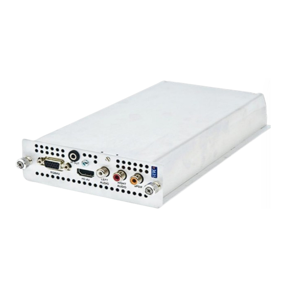
AvediaStream e2635/e3635 and e2655/e3655 Encoders V1.1 Encoder Rear Panel Interfaces The AvediaStream e26xx and e36xx encoders support the following inputs and outputs: Table 3 Encoder Rear Panel Interfaces Video Inputs e2635/e3635 e2655/e3655 HD Component ● SD Component ● ● HD AV ●... - Page 14 AvediaStream e2535/e3635 and e2655/e3655 Encoders V1.1 AvediaStream e2635/e3635 Interface The AvediaStream e2635 and e3635 encoders provide video and audio inputs as shown in Figure 2. Figure 2 AvediaStream e3635 Encoder – Rear Panel Video Inputs The e2635 and e3635 support the following video input types: ●...
- Page 15 AvediaStream e2635/e3635 and e2655/e3655 Encoders V1.1 AvediaStream e2655/e3655 Interface The AvediaStream e2655 and e3655 encoders provide a Serial Digital Interface video input with embedded or S/PDIF audio inputs. SDI Loop-through is also available. Connections are shown in Figure 3 below. Figure 3 AvediaStream e3655 Encoder –...
- Page 16 AvediaStream e2535/e3635 and e2655/e3655 Encoders V1.1 SDI Interface (OUT) The SDI (OUT) interface is a loop-through interface to enable you to connect the same SDI input to another device. Connect using a BNC connector. This output is disabled by default, and can be configured via the web interface Input page.
-
Page 17: Management Interfaces
AvediaStream e2635/e3635 and e2655/e3655 Encoders V1.1 3 Management Interfaces The encoder has four management interfaces, as follows: ● Web Management Interface ● Admin Interface ● AvediaServer Director Note: Each encoding module in a chassis must be configured independently. Web Management Interface You can manage every aspect of the encoder’s functionality using the Web Management Interface. - Page 18 AvediaStream e2535/e3635 and e2655/e3655 Encoders V1.1 Figure 5 Web Management Interface 3. Clicking on the encoder name on the left hand side reveals the menu. Use this menu to navigate through the pages, changing settings as required. Click the Apply button on each page to save your changes.
-
Page 19: Admin Interface
AvediaStream e2635/e3635 and e2655/e3655 Encoders V1.1 Admin Interface In certain circumstances it may not be possible to manage an encoder via the Web Management Interface. For these situations, a text-based Admin Interface is provided, which is available via the serial interface (marked ‘admin’ on the chassis front panel) or via telnet. Figure 7 Admin Interface For more information on the use of the Admin Interface, refer to Section 5 - Admin Interface on page 30. - Page 20 AvediaStream e2535/e3635 and e2655/e3655 Encoders V1.1 The AvediaServer Director can perform the following actions: ● Name - specify the Encoder name ● Location – specify the Encoder location ● Reboot – re-start the Encoder ● Ping – Ping the Encoder ●...
-
Page 21: General Device Management
AvediaStream e2635/e3635 and e2655/e3655 Encoders V1.1 4 General Device Management This section of the manual describes how to manage attributes of the encoder not associated with IPTV streaming. For example, you will find out how configure IP addressing, and how to upgrade firmware. -
Page 22: Device Naming
AvediaStream e2535/e3635 and e2655/e3655 Encoders V1.1 Device Naming The encoder can be assigned a name and location. These can help identify the device in the AvediaServer Director application. To specify the name and location: 1. Click General. 2. Enter a name and location as appropriate in the Name: and Location: fields. - Page 23 AvediaStream e2635/e3635 and e2655/e3655 Encoders V1.1 Device IP addressing You can configure the encoder to obtain an IP address automatically using DHCP, or you can specify static addressing information i.e. IP address, subnet mask and default gateway. Note: After applying an IP addressing change, this change takes effect after a short time and the device starts using the new IP address.
-
Page 24: Authentication
AvediaStream e2535/e3635 and e2655/e3655 Encoders V1.1 Authentication Admin Password You can control access to the web management interface and admin interface by changing the password. These options are all available from the Authentication page in the web interface shown in Figure 11. -
Page 25: Maintenance
3. Click the Apply button. Specifying the SNMP Trap Manager IP Address SNMP traps are mainly used as device discovery messages; they enable Exterity’s management applications to discover devices on the network. These traps are always broadcast to 255.255.255.255. They are also transmitted to an additional configurable destination. - Page 26 AvediaStream e2535/e3635 and e2655/e3655 Encoders V1.1 Restarting the Encoder You can restart the encoder at any time. To restart the encoder, click Maintenance and click the Reboot Encoder button. Upgrading the Encoder Firmware By upgrading the encoder’s firmware regularly, you can ensure that you are always using the most recent version.
- Page 27 AvediaStream e2635/e3635 and e2655/e3655 Encoders V1.1 Export/import Configuration Settings Once you have configured the encoder, you can store your configuration settings in a single file. You can use the file to restore your settings should you need to. You can also use a saved configuration to replicate identical settings on multiple devices.
-
Page 28: Logging
AvediaStream e2535/e3635 and e2655/e3655 Encoders V1.1 Logging The encoder saves historical information about internal events within the device to its log file. This can be useful in troubleshooting problems with the device. It is also possible to send these log messages to a remote syslog server. - Page 29 AvediaStream e2635/e3635 and e2655/e3655 Encoders V1.1 Remote logging To send device log information to a remote server, you need to install a syslog server application on the remote server. Then set up the remote logging function on the encoder as described below.
-
Page 30: Admin Interface
AvediaStream e2535/e3635 and e2655/e3655 Encoders V1.1 5 Admin Interface In certain circumstances it may not be possible to manage an encoder via its web interface. For these situations a text based admin interface is provided which is available via the serial interface (marked ADM on the chassis front panel) or via telnet. - Page 31 AvediaStream e2635/e3635 and e2655/e3655 Encoders V1.1 Set admin password Allows the administrator to change the admin password for the serial and web interfaces Run a shell This allows the administrator to run a shell as admin. Return to factory defaults This page allows the administrator to set all configurations to factory defaults.
-
Page 32: Encoding And Streaming
AvediaStream e2535/e3635 and e2655/e3655 Encoders V1.1 6 Encoding and Streaming This section of the manual describes how to manage those aspects of the encoder related to taking the analogue or digital AV inputs and converting them to an IPTV stream. All procedures described in this section assume that you are using the Web interface, as described on page 17, to configure the AvediaStream encoders. - Page 33 AvediaStream e2635/e3635 and e2655/e3655 Encoders V1.1 Figure 16 AvediaStream e3635 – Source Page Manual Controls Video Input You must select the Video Input to match the applied video input and physical connection to the encoder. Valid input options are HDAV, RGBHV and Component (YPbPr). For more information about the video input connections refer to the AvediaStream e2635/e3635 Interface on Page 14.
- Page 34 AvediaStream e2535/e3635 and e2655/e3655 Encoders V1.1 To specify the Preferred Input Resolution: 1. Click Source. 2. With RGBHV or HDAV as the configured video input, select the required value from the Preferred Input Resolution drop down list. 3. Click the Apply button.
- Page 35 AvediaStream e2635/e3635 and e2655/e3655 Encoders V1.1 7. Click the Apply button. Audio Input Audio Input specifies the type of audio applied to the encoder. Valid settings are Analog, S/PDIF, and HDAV. HDAV audio is not available for RGBHV video input. Refer to the AvediaStream e2635/e3635 Interface on page 14 for more information about audio connections.
-
Page 36: Audio/Video Input - Avediastream E2655 /E3655
AvediaStream e2535/e3635 and e2655/e3655 Encoders V1.1 Audio/Video Input – AvediaStream e2655 /e3655 The Audio/Video Input is configured from the Input page on the web interface as shown in Figure 17. Figure 17 AvediaStream e3655 – Input Page SDI Input The AvediaStream e2655 and e3655 encoders support SDI SMPTE 259M, SDI SMPTE 292M and SDI SMPTE 424M input and are compatible with SDI sources which have output frame rates of 23.98Hz, 24Hz, 50Hz, 59.94Hz, and 60Hz. - Page 37 AvediaStream e2635/e3635 and e2655/e3655 Encoders V1.1 To specify the audio input: 1. Click Source. 2. Choose an option from the Audio Input drop down list. 3. Click the Apply button. SDI Audio Group and Channel When Embedded is selected, the module extracts the audio from the SDI stream. Configure the Group and Channel settings to select the required audio from the 8 possible stereo pairs.
-
Page 38: Encoding
AvediaStream e2535/e3635 and e2655/e3655 Encoders V1.1 Encoding Encoding configuration is common to the e2635/55 and e3635/55 encoders. The output video stream can be encoded to either MPEG-2 or H.264 (MPEG-4 Part 10) standard. Scaling capabilities of the e2635/55 and e3635/55 enable the input signal to be output in a variety of resolutions and frame rates with stream bit rates ranging between 128kbps and 20Mbps using either constant or variable bit rate encoding. - Page 39 AvediaStream e2635/e3635 and e2655/e3655 Encoders V1.1 To select and configure CBR: 1. Click Encoding. 2. Click the Bit Rate Mode drop down list to select Constant. 3. Click the Bit Rate drop down list to select a value from 128 kbps to 20 Mbps 4.
- Page 40 AvediaStream e2535/e3635 and e2655/e3655 Encoders V1.1 To specify the audio standard: 1. Click Encoding. 2. Click the Audio Standard drop down list to select Unchanged (e2655/e3655 only), MP2, or AAC. 3. Click the Apply button. Audio Bit Rate The bit rate can be set to values from 48kbps to 384kbps.
- Page 41 AvediaStream e2635/e3635 and e2655/e3655 Encoders V1.1 Test Pattern You can configure the AvediaStream e2635/55 and e3635/55 encoders to output a selection of test patterns continuously, or only when no input signal is detected. Test patterns can be useful during system commissioning when no other content is available, or to highlight the lack of an input signal.
- Page 42 AvediaStream e2535/e3635 and e2655/e3655 Encoders V1.1 Test Pattern Mode You can set the AvediaStream e2635/55 and e3635/55 encoders to output a test pattern continuously (Always On), or when no input signal is detected (On when No Input). Select Off (default) to turn the test pattern off.
- Page 43 AvediaStream e2635/e3635 and e2655/e3655 Encoders V1.1 Overlay The Overlay page allows up to 64 characters of text to be displayed over the streamed video or test pattern. The text can be displayed continuously only when no signal is detected at the input or disabled.
- Page 44 4. Click the Apply button. Logo Display You can display an uploaded file or use the default Exterity logo. To upload and use your own logo file, it must be placed in the root folder of the TFTP server path specified on the Maintenance page.
- Page 45 AvediaStream e2635/e3635 and e2655/e3655 Encoders V1.1 7x 18 84 x 432 6 x 21 72 x 504 5 x 25 60 x 600 4 x 31 48 x 744 3 x 42 36 x 1008 2 x 63 24 x 1512 1 x 127 12 x 3048 Logo files are uploaded to the encoder using TFTP and are listed on the Resources page.
- Page 46 2. Click the check boxes for each individual file you want to remove, or click the check box beside the Delete button to select all files. 3. Click the Delete button. 4. Click the Restore Defaults button to re-list the default Exterity Logo if required. Administrator’s Guide...
-
Page 47: Channel Announcements
Figure 23 AvediaStream Encoder – Announcements Page Channel name The channel name will be used by Exterity IPTV receivers and PC clients to identify the channel. The default channel name for the AvediaStream e3635 is “AvediaStream e3635 xxxxx”, where “xxxxxx” is the last six digits of the encoder’s MAC address. The AvediaStream e2635/55 and e3655 are similar. - Page 48 AvediaStream e2535/e3635 and e2655/e3655 Encoders V1.1 To add the device to a group or groups: 1. Click Announcements. 2. Enter a comma separated list of group names, for example; sport,children in the Groups box. 3. Click the Apply button. Note: When entering a list of group names as a comma separated list, ensure there are no spaces in the list.
-
Page 49: Stream Properties
AvediaStream e2635/e3635 and e2655/e3655 Encoders V1.1 Stream Properties The AvediaStream encoders can send their streams to the default multicast address, or to a specified multicast or unicast address. Stream Properties are configured using the web interface Stream page as shown in Figure 24. Figure 24 AvediaStream Encoder –... - Page 50 AvediaStream e2535/e3635 and e2655/e3655 Encoders V1.1 4. Click the Apply button. Figure 25 AvediaStream Encoder – Manual Stream Address Port By default, the stream is sent to the UDP port 5000. The port can be altered as required. To specify the port: 1.
- Page 51 AvediaStream e2635/e3635 and e2655/e3655 Encoders V1.1 For example, as shown in Table 4, to specify a DCSP (decimal) value of 1 you must left shift the binary value by 2 bits and enter a value of 4 in the IP TOS/Diffserv entry field. Refer to RFC 2474 for more detailed information.
-
Page 52: Status Monitoring
AvediaStream e2535/e3635 and e2655/e3655 Encoders V1.1 7 Status Monitoring This section explains how to check the operating status of an AvediaStream encoder. You can see both configured and detected information and check, for example, if the encoder is streaming the signal applied to the input. -
Page 53: Network Statistics
AvediaStream e2635/e3635 and e2655/e3655 Encoders V1.1 Source: The configured and detected input signal information is displayed in the form: <selected input> - <status> Refer to Encoding and Streaming on page 32 for more information about input selection. Video Format: The Encoder detects and displays the resolution and frame rate of the input signal. Audio Format: The Encoder detects and displays the audio input and sampling rate of the input. -
Page 54: Troubleshooting
AvediaStream e2535/e3635 and e2655/e3655 Encoders V1.1 8 Troubleshooting Problem Possible Cause Solution Device does not appear in AvediaServer Network connection faulty or cannot Check Ethernet connections or replace Director. obtain IP address. cable. Check that DHCP Server is running on network. -
Page 55: Appendix A Serial Interface Connection
The serial admin interface provides the ability to manage a small subset of device functionality e.g. to configure an IP address. Cabling To connect to the serial interface use the DB-9 – RJ45 adaptor supplied by Exterity (shown in Figure 28. Figure 28 DB-9 to RJ45 serial adaptor The female DB-9 connector should be plugged into the serial port on a PC. - Page 56 AvediaStream e2535/e3635 and e2655/e3655 Encoders V1.1 Opening a Session Open a terminal program such as Hyperterminal (this can be found on a standard Windows PC). Set up the serial port with the following settings (see example in Figure 30): ●...
-
Page 57: Appendix B Support And Contact Information
AvediaStream e2635/e3635 and e2655/e3655 Encoders V1.1 APPENDIX B Support and Contact Information Technical Support for Exterity products is provided by authorised Systems Integrators and Resellers. Please contact your Systems Integrator or Reseller with any Support issues. Administrator’s Guide...
Need help?
Do you have a question about the AvediaStream e3635 and is the answer not in the manual?
Questions and answers