
Related Manuals for MDS SD9


Summary of Contents for MDS SD9
- Page 1 MDS SD Series Secure, Long Range Data Communications Covering Units Operating in x710 Mode with Firmware Version 4.x MDS 05-4670A01, Rev. E MARCH 2015...
- Page 2 Need Quick-Start instructions for this product? Please refer to publication 05-4669A01. All GE MDS user guides are available online at www.gemds.com...
-
Page 3: Table Of Contents
5.1 Initial Startup & Checkout ......................19 5.2 Initial Software Configuration .......................19 Serial vs. Telnet Access, and the Device Manager................20 Connecting a PC & Setting Basic Parameters................20 6.0 TRANSCEIVER MANAGEMENT..................21 6.1 Software Commands ........................21 MDS 05-4670A01, Rev. E SD Series Reference Manual (x710 Mode) - Page 4 RMODE [X710, TRANSPARENT, PACKET, CMAC, HELP] ............34 RSSI...............................34 RTSKEY [ON, OFF] ........................35 RTU [ON/OFF/0-80] ........................35 RX [xxx.xxxx] ..........................35 RXATTN [ON or OFF] ........................35 RXLEVEL [–20 to 0]........................35 RXTOL [NORMAL or CUSTOM] ....................36 MDS 05-4670A01, Rev. E SD Series Reference Manual (x710 Mode)
- Page 5 9.0 GLOSSARY OF TERMS..................... 56 Copyright and Trademark This manual and all software described herein is protected by Copyright: 2012 GE MDS, LLC. All rights reserved. GE MDS, LLC reserves its right to correct any errors and omissions in this publi- ® cation. Modbus is a registered trademark of Schneider Electric Corporation.
-
Page 6: Rf Safety Notice (English And French)
2.02 meters for a 7 dBd (9.15 dBi) antenna. Safety Distance (SD1) Use of higher gain antennas means increasing the distance accordingly. For SD2, maintain an RF safety distance of 1.89 meters for a 7 dBd (9.15 dBi) antenna. Safety Distance (SD2) Use of higher gain antennas means increasing the distance accordingly. -
Page 7: Environmental Information
These systems will reuse or recycle most of the materials found in this equipment in a sound way. Please contact GE MDS or your supplier for more information on the proper dis- posal of this equipment. - Page 8 A power connector with screw-type retaining screws as supplied by GE MDS must be used. Do not disconnect equipment unless power has been switched off or the area is known to be non-hazardous.
- Page 9 ANY THEORY OF LIABILITY, WHETHER IN CONTRACT, STRICT LIABILITY, OR TORT (INCLUDING NEGLIGENCE OR OTHERWISE) ARISING IN ANY WAY OUT OF THE USE OF THIS SOFTWARE, EVEN IF ADVISED OF THE POSSIBILITY OF SUCH DAMAGE. MDS 05-4670A01, Rev. E SD Series Reference Manual (x710 Mode)
- Page 10 SD Series Reference Manual (x710 Mode) MDS 05-4670A01, Rev. E...
-
Page 11: Introduction
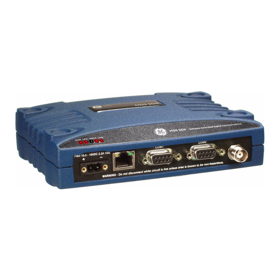
1.0 INTRODUCTION This Reference Manual is one of two books provided for users of the MDS SD Series Transceiver (Figure 1) operating in x710 Mode. It con- tains an overview of common applications, installation planning data, technical specifications, troubleshooting, and a listing of software com- mands. -
Page 12: Electronic Manuals
All SD Series manuals are available in printed or electronic form. Download electronic manuals from our web site at www.gemds.com. The web site also contains links to Application Bulletins and other product information. SD Series Reference Manual (x710 Mode) MDS 05-4670A01, Rev. E... -
Page 13: Product Description
Data interface connections can be made for both serial (RS-232/RS-485) and local Ethernet protocols. The radio’s x710 Mode is designed primarily for use in serial MDS x710 radio networks where a central station communicates with each remote, one at a time, to convey data and control signals. For models operating... -
Page 14: Key Product Features
• Standard—All features except Ethernet functionality • x710—Direct, drop-in compatibility for networks using a mix of SD and older MDS x710 radios. The Ethernet port is available for radio management in x710 mode, but not for payload. The unit’s complete model number is printed on the bottom label. Addi-... -
Page 15: Operating Modes And Applicable Manuals
MDS x710 (4710 or 9710) transceivers, and uses the same core command set as these radios. It is ideal for use in systems containing a mix of newer SD radios and legacy MDS x710 units. This manual covers x710 Mode radios. -
Page 16: Accessories And Spares
2.5 Accessories and Spares Table 1 lists common accessories and spare items for the transceiver. GE MDS also offers an Accessories Selection Guide listing additional items that can be used with the product. Contact your factory represen- tative or visit to obtain a copy of the guide. -
Page 17: Point-To-Point System
Master and the other as a Remote (see Figure 5). It provides a simplex or half-duplex communications link for the transfer of data between two locations. Invisible place holder Figure 5. Typical Point-to-Point Link MDS 05-4670A01, Rev. E SD Series Reference Manual (x710 Mode) -
Page 18: Continuously-Keyed Versus Switched-Carrier Operation
NOTE: Data turn-around times are increased when inter-working with an MDS x710 network. This restriction does not apply to homogeneous SD networks. 4.0 INSTALLATION PLANNING Careful planning of the installation site helps achieve optimal performance from the transceiver. -
Page 19: Mounting Options
Figure 7. An optional 35 mm DIN rail mounting bracket is also available. See “Optional DIN Rail Mounting” on page 10. Invisible place holder 6.675˝ (16.95 cm) Figure 7. Mounting Bracket Dimensions MDS 05-4670A01, Rev. E SD Series Reference Manual (x710 Mode) -
Page 20: Optional Din Rail Mounting
Release Tab. Figure 9. Attachment & Mounting of DIN Rail Bracket (unit shown is for example only, and is not an SD Transceiver) SD Series Reference Manual (x710 Mode) MDS 05-4670A01, Rev. E... -
Page 21: Antennas And Feedlines
Antennas of this type are available from several manufacturers, including GE MDS. Contact your factory representative for details. Invisible place holder Figure 10. Typical Yagi Antenna (mounted to mast) Feedlines The selection of an antenna feedline is very important. -
Page 22: Dc Power Connection
Be sure to observe proper polarity as shown in Figure 11. Figure 11. DC Power Connector (P/N 73-1194A39) NOTE: The radio is designed for use in negative ground systems only. SD Series Reference Manual (x710 Mode) MDS 05-4670A01, Rev. E... -
Page 23: Grounding Considerations
As viewed from outside the radio NOTE: To prevent unintended keying of the transmitter during management , or do not connect to Pin 6 of the activities, set PTTSIG port. COM1 MDS 05-4670A01, Rev. E SD Series Reference Manual (x710 Mode) -
Page 24: Com1 In Analog Operation
Pins 4, 5, 6, and 8 in Table 5 are used for analog oper- ation. (Pins 7 and 9 are reserved for user I/O signals.) Refer to “Analog Operation of the Transceiver” on Page 46 for more information. SD Series Reference Manual (x710 Mode) MDS 05-4670A01, Rev. E... -
Page 25: Com2 (Data) Connections
As viewed from outside the radio Table 7 lists the port pin functions when configured to operate in Pin Descriptions— COM2 RS/EIA-232 Mode RS/EIA-232 mode. NOTE: The radio is hard-wired as a DCE device. MDS 05-4670A01, Rev. E SD Series Reference Manual (x710 Mode) - Page 26 A high on this pin indicates an alarm condition; a low indicates normal operation. RXD+/RXB (Received Data +)— Non-inverting receiver input TXD+/TXB (Transmitted Data +)—Non-inverting driver output. Reserved—User I/O for special applications SD Series Reference Manual (x710 Mode) MDS 05-4670A01, Rev. E...
-
Page 27: Ethernet Interface (Rj-45)
(As viewed from the outside of the unit) Table 9. Ethernet Port (IP/Ethernet) Pinouts Functions Ref. Transmit Data (TX) High Transmit Data (TX) Receive Data (RX) High Unused Unused Receive Data (RX) Unused Unused MDS 05-4670A01, Rev. E SD Series Reference Manual (x710 Mode) -
Page 28: Step-By-Step Installation
NOTE: To comply with IEC61850-3, paragraph 5.7.1.2, surge suppression must be used across the power supply for Class 3 and 4 severity levels as defined by IEC 61000-4-5 Annex A. SD Series Reference Manual (x710 Mode) MDS 05-4670A01, Rev. E... -
Page 29: Initial Startup & Checkout
There are numerous settings that go beyond basic configuration, and you may wish to access these later. A full description of commands is provided in “TRANSCEIVER MANAGEMENT” on Page 21. MDS 05-4670A01, Rev. E SD Series Reference Manual (x710 Mode) -
Page 30: Serial Vs. Telnet Access, And The Device Manager
8 bits, no parity, one stop bit (8N1), flow control disabled, VT100 emulation. The radio’s COM1 port automatically determines the connected baud rate (within the range of 1200–115200 bps). The preferred baud rate is 9600 bps. SD Series Reference Manual (x710 Mode) MDS 05-4670A01, Rev. E... -
Page 31: Transceiver Management
The Authorization Key and a list of authorized features. ALARM Details Page 25 Read current operating condition of radio. AMASK [0000 0000–FFFF Set/display hex code identifying which events FFFF] Details Page 25 trigger an alarm. MDS 05-4670A01, Rev. E SD Series Reference Manual (x710 Mode) - Page 32 P-20 Protected Network Chassis. INIT [SDx] Details Page 30 Configure radio for use outside of the Protected Network Chassis (SDxP). Restores certain transceiver defaults changed by the INIT P-20 command. SD Series Reference Manual (x710 Mode) MDS 05-4670A01, Rev. E...
- Page 33 Set/display receiver frequency. Page 35 RXATTN [ON or OFF] Enables or disables receive attenuation. Details Page 35 Set/display the receive audio input level. RXLEVEL [–20 to 0] Details Page 35 MDS 05-4670A01, Rev. E SD Series Reference Manual (x710 Mode)
-
Page 34: Detailed Command Descriptions
This section provides detailed information for the user commands previously listed in Table 11 (Page 21). SD Series Reference Manual (x710 Mode) MDS 05-4670A01, Rev. E... -
Page 35: Alarm
Authorization Key The transceiver’s feature set may be expanded (if all features are not currently enabled) by entering a new authorization key, which can be purchased from GE MDS. Contact the factory to obtain a new Authori- zation Key. ALARM command displays a summary of the radio’s current oper-... -
Page 36: Audio [On, Off]
RF data frame is disassembled. Average and typ- ical latency will be minimized, but idle character gaps may be intro- duced into the outgoing data flow. SD Series Reference Manual (x710 Mode) MDS 05-4670A01, Rev. E... -
Page 37: Ckey [On-Off]
0, which means that CTS will drop immediately after the last character is transmitted. If the command is entered when the radio is in mode, the response is shown. DEVICE DCE CTSHOLD N/A MDS 05-4670A01, Rev. E SD Series Reference Manual (x710 Mode) -
Page 38: Datakey [On, Off]
DLINK OFF ables the diagnostic link. To change the diagnostic link, enter followed by one of the fol- DLINK lowing baud rates: 1200, 2400, 4800, 9600, 19200 (default), 38400, 57600, 115200. SD Series Reference Manual (x710 Mode) MDS 05-4670A01, Rev. E... -
Page 39: Dtype [Node/Root]
FORCEDCD [ON or OFF] Forces Data Carrier Detect (DCD) to always be asserted. Use when con- Force DCD necting to equipment that requires a constant DCD indication. HELP Show available commands. User Help MDS 05-4670A01, Rev. E SD Series Reference Manual (x710 Mode) -
Page 40: Init
Initialization for P-20 Implementation chassis by setting the following parameters to the values shown below: ASENSE ACTIVE LO (trigger on major alarms) AMASK FFFF 0000 (20 minute receive time-out timer) RXTOT SD Series Reference Manual (x710 Mode) MDS 05-4670A01, Rev. E... -
Page 41: Ipconfig
MODEM xxxx xxxx the radio. Table 12 shows the supported modem types. NOTE:For compatibility with an existing MDS x710 system, make sure to select the matching type. See Table 11. MODEM Table 12. Modem Selection vs. Speed, Bandwidth & Sensitivity... - Page 42 4) Only available for SD2 and SD9 units with wide bandwidth hardware option. Sensitivity is -104 dBm for SD2 and -100 dBm for SD9. 5) SD1 sensitivity may be up to 2 dB less, due to MDS 1710 interoperability constraints.
-
Page 43: Owm [Xxx
When the transceiver is used to replace an existing MDS x710 radio, it is important to verify that the modem selection is compatible with the unit replaced. Table 13 lists SD modem type selections and the compat- ible x710 models they can be used with. -
Page 44: Port [Rs232, Rs485]
This command continuously displays the radio’s Received Signal Received Signal Strength Indicator Strength Indication (RSSI) in dBm, until you press the Enter key. Incoming signal strengths up to -60 dBm can be read. SD Series Reference Manual (x710 Mode) MDS 05-4670A01, Rev. E... -
Page 45: Rtskey [On, Off]
RX Audio Output selects or shows the desired receive audio output RXLEVEL command Level level. For more information, refer to the detailed description of analog operation beginning on Page 46. MDS 05-4670A01, Rev. E SD Series Reference Manual (x710 Mode) -
Page 46: Rxtol [Normal Or Custom]
Enter key. As used in this guide, the signal-to-noise measurement is based upon the signal level following equalization, for received frames. SD Series Reference Manual (x710 Mode) MDS 05-4670A01, Rev. E... -
Page 47: Spectrum [Xxx.xx]
Figure 18. Internal Spectrum Analyzer Display SQUELCH [AUTO, BYPASSED] Squelch Operation Set or show analog squelch bypass. SREV Software/Firmware This command shows the software revision level of the transceiver firm- Revision Level ware. MDS 05-4670A01, Rev. E SD Series Reference Manual (x710 Mode) -
Page 48: Stat
• can be used to check on the progress of the down- TFTP STATUS load. TEMP Internal This command shows the internal temperature of the transceiver in Temperature degrees Celsius. SD Series Reference Manual (x710 Mode) MDS 05-4670A01, Rev. E... -
Page 49: Tot [1-255, On, Off]
UPTIME Displays time since last system reboot. Up Time VERSION Displays package version information for each firmware image. Firmware Version MDS 05-4670A01, Rev. E SD Series Reference Manual (x710 Mode) -
Page 50: Troubleshooting
If an alarm does exist, a two-digit alarm code (01–31) is shown and the event is identified as a Major or Minor Alarm. A brief description of the alarm is also given. MDS 05-4670A01, Rev. E SD Series Reference Manual (x710 Mode) -
Page 51: Major Alarms Vs. Minor Alarms
The codes shown are a subset of a larger pool of codes used for various GE MDS products. For this reason, the table does not show a sequential listing of all code numbers. Only the codes applicable to this product are shown, and this list is subject to change with product revi- sion. - Page 52 Description Minor A socket operation failed. Minor AP not available. Status Forced restart of Ethernet interface. Status Reprogramming in progress. Inform Firmware update successful. Inform Reprogramming aborted. Inform Remote rebooted. SD Series Reference Manual (x710 Mode) MDS 05-4670A01, Rev. E...
-
Page 53: Technical Reference
Carrier Power: 0.1 Watts to 5 Watts Power Measurement Accuracy: +/- 1.5 dB NOTE: RF output is limited to 2 watts for SD2 radios operating in Band B (220-222 MHz). MDS 05-4670A01, Rev. E SD Series Reference Manual (x710 Mode) - Page 54 Fuse: 5 A, internal ENVIRONMENTAL Humidity: SD1: 95% at 70°C (158°F), non-condensing SD2: 95% at 40°C (104°F), non-condensing SD4: 95% at 70°C (158°F), non-condensing SD9: 95% at 40°C (104°F), non-condensing Temperature Range: –40 to 70°C (–40°F to 158°F) Weight (nominal): 1.22 lbs.
-
Page 55: Performing Network-Wide Remote Diagnostics
A complete explanation of remote diagnostics can be found in the Net- work-Wide Diagnostics System Handbook (Part No. 05-3467A01). See the Handbook for more information about the basic diagnostic proce- dures outlined below. MDS 05-4670A01, Rev. E SD Series Reference Manual (x710 Mode) -
Page 56: User-Programmable I/O Functions - Pending
The transceiver is designed for full digital modulation, while offering analog support to those systems that require it. Operation is compatible with the MDS x710 family of products, but some SD radio-specific command configuration and wiring might be necessary based on differ- ences in SD hardware. -
Page 57: Physical Interface
In analog-only mode, carrier detect is based on squelch status. Mixed analog/digital operation is useful for orderwire application, or for analog systems that need to make use of GE MDS Network-Wide Diag- nostics. Operation is enabled by selecting a digital modem type (for example, ) and selecting . -
Page 58: Upgrading The Radio's Firmware
SQUELCH AUTO 8.5 Upgrading the Radio’s Firmware From time to time, GE MDS releases new firmware for its radio prod- ucts to take advantage of engineering improvements or to add opera- tional features. New firmware can be installed into existing radios in the field, bringing them up to date with the firmware shipped with new units. -
Page 59: Web Method
In the space provided, enter the file to reprogram into this radio, *.mpk then click to start the file upload process. Do not click away Program from this page until the upload has finished processing. MDS 05-4670A01, Rev. E SD Series Reference Manual (x710 Mode) -
Page 60: Tftp Method
(a Windows-based TFTP .mpk server can be downloaded from the GE MDS Web site at: www.gemds.com/Resources/TechnicalSupport 3. The IP address of the PC running the TFTP server. If you do not know your computer’s IP address, use the... - Page 61 LED on the radio’s port lights and stays lit. This verifies that the network is functioning. 2. Launch the TFTP server on the PC. If using the GE MDS TFTP Server, click the tab (A in Figure 22 below) and modify the...
-
Page 62: Serial Transfer Method
(included with many pre-Vista PCs). Connect a PC to the radio’s Serial connector as shown in Connecting the COM1 Transceiver for Figure 23 to prepare for firmware upgrade. Firmware Upgrade MDS 05-4670A01, Rev. E SD Series Reference Manual (x710 Mode) - Page 63 LOADER> This completes the serial upgrade procedure. To verify that the radio is running the newly loaded firmware image, enter the com- srev mand after rebooting. MDS 05-4670A01, Rev. E SD Series Reference Manual (x710 Mode)
-
Page 64: Error Messages During File Transfers
Bad CRC Cyclic Redundancy Check reporting a corrupted file. Attempt to re-load, or use a different file. Version String Mismatch Invalid file detected. Attempt to re-load, or use a different file. MDS 05-4670A01, Rev. E SD Series Reference Manual (x710 Mode) -
Page 65: Dbm-Watts-Volts Conversion Chart
-136 10mW -137 2.25 .1 W -138 6.4mW .001nW -139 .500 -140 .01ƒW .445 5.75 .400 3.2mW .355 2.5mW 1.25 .320 2.0mW 1.18 .280 1.6mW 1.00 3.51 .252 1.25mW 0.90 MDS 05-4670A01, Rev. E SD Series Reference Manual (x710 Mode) -
Page 66: Glossary Of Terms
Equipment). In data communications terminology, this is the “modem” side of a computer-to-modem connection. The transceiver described in this manual is hardwired as a DCE device. Digital Signal Processing—See DSP. SD Series Reference Manual (x710 Mode) MDS 05-4670A01, Rev. E... - Page 67 Multiple Address System—See MAS. Network-Wide Diagnostics—An advanced method of controlling and interrogating GE MDS radios in a radio network. Non-intrusive diagnostics—See Passive messaging. MDS 05-4670A01, Rev. E SD Series Reference Manual (x710 Mode)
- Page 68 SWR—Standing Wave Ratio. A parameter related to the ratio between forward transmitter power and the reflected power from the antenna system. As a general guideline, reflected power should not exceed 10% of the forward power (≈ 2:1 SWR). SD Series Reference Manual (x710 Mode) MDS 05-4670A01, Rev. E...
- Page 69 NOTES MDS 05-4670A01, Rev. E SD Series Reference Manual (x710 Mode)
- Page 70 SD Series Reference Manual (x710 Mode) MDS 05-4670A01, Rev. E...
- Page 71 DLINK command 28 RSSI (display RSSI) 34 use of 46 RTU (enable/disable internal RTU) 35 Downloading new software 48 RX (set/display receive frequency) 35 DSP (Digital Signal Processing), defined 57 MDS 05-4670A01, Rev. E SD Series Reference Manual (x710 Mode)
- Page 72 (DKEY command) 28 checking for alarms (STAT command) 40 switched carrier, defined 8 downloading new software 48 entering commands using the Hand-Held Terminal (HHT) 21 Latency, defined 57 MDS 05-4670A01, Rev. E SD Series Reference Manual (x710 Mode)
- Page 73 8 Sleep mode shown by PWR LED status indicator 19 SNR command 36 Software diagnostics and control used from PC 48 display revision level 37 upgrading 48 Specifications MDS 05-4670A01, Rev. E SD Series Reference Manual (x710 Mode)
- Page 74 MDS 05-4670A01, Rev. E SD Series Reference Manual (x710 Mode)
-
Page 75: In Case Of Difficulty
SRO numbers are issued online at www.gedigitalenergy.com/Communications.htm. On the left side of the page, click “Login to my MDS” and once logged in, click “Service Request Order”. Your number will be issued immediately after the required information is entered. Please be sure to have the model number(s), serial number(s), detailed reason for return, “ship to”... - Page 76 GE MDS, LLC 175 Science Parkway Rochester, NY 14620 Telephone: +1 585 242-9600 FAX: +1 585 242-9620 www.gemds.com...
Need help?
Do you have a question about the SD9 and is the answer not in the manual?
Questions and answers