Table of Contents
Advertisement
FURNACE MODELS: SATURN™ 140 and SATURN™ 230
PUBLICATION DATE: 6/13/11, Rev. 3
WARNING: DO NOT assemble, install, operate, or maintain this equipment without first
reading and understanding the information provided in this manual. Installation and
service must be accomplished by qualified personnel. Failure to follow all safety precautions
and procedures as stated in this manual may result in property damage, serious personal injury
or death.
IMPORTANT FOR U.S. INSTALLATIONS: All installations must be made in accordance with state and local codes
which may differ from the information provided in this manual. Save these instructions for reference.
IMPORTANT FOR CANADIAN INSTALLATIONS: These instructions have been reviewed and accepted by
Underwriters' Laboratories of Canada as being appropriate for the installation of the ULC labelled products
identified herein. The use of these instructions for the installation of products NOT bearing the ULC label and
NOT identified herein may result in an unacceptable or hazardous installation.
IMPORTANT FOR CANADIAN INSTALLATIONS: The installation of this equipment is to be accomplished by
qualified personnel and in accordance with the regulation of authorities having jurisdiction and CSA Standard B 139,
Installation Code for Oil Burning Equipment.
OPERATOR'S MANUAL
MULTI-OIL FURNACES
with SATURN™ 125 BURNER
U.L. Listed Used Oil
Burning Appliance
#MH15393 (N)
U.L.-C Listed
#CMP217
CLEAN BURN PART # 43224
Advertisement
Table of Contents

Related Manuals for Saturn 140

Summary of Contents for Saturn 140
- Page 1 OPERATOR'S MANUAL FURNACE MODELS: SATURN™ 140 and SATURN™ 230 MULTI-OIL FURNACES with SATURN™ 125 BURNER U.L. Listed Used Oil Burning Appliance #MH15393 (N) U.L.-C Listed #CMP217 PUBLICATION DATE: 6/13/11, Rev. 3 CLEAN BURN PART # 43224 WARNING: DO NOT assemble, install, operate, or maintain this equipment without first reading and understanding the information provided in this manual.
-
Page 3: Warranty Information
TRADEMARKS The Clean Burn logo and Saturn logo are trademarks of Clean Burn, LLC. All other brand or product names mentioned are the registered trademarks or trademarks of their respective owners. -
Page 5: Table Of Contents
TABLE OF CONTENTS SECTION 1: INTRODUCTION ..................1-1 Guide to this Manual ......................1-1 For Your Safety........................ 1-2 Guidelines for Furnace Usage ................... 1-4 Guidelines for Used Oil Tanks .................. 1-5 Safety Labels ......................1-6 SECTION 2: UNPACKING ..................2-1 Removing the Shipping Crate .................... - Page 6 TABLE OF CONTENTS SECTION 4: FURNACE INSTALLATION (continued) Wiring the Furnace and Pump ................... 4-12 Wiring to the Furnace ....................4-12 Wiring to the Metering Pump ..................4-12 Installing the Suction Oil Line Components ................ 4-13 Installing the Pressure Relief Oil Line Back to the Tank ............. 4-16 Installing the Pressure Oil Line Components ..............
- Page 7 Metering Pump Components ................... A-16 APPENDIX B Wiring Diagrams ....................... B-1 Furnace Wiring Diagram ..................... B-1 Saturn™ 125 Burner Wiring Diagram ................. B-2 Ladder Schematic ...................... B-3 Metering Pump Wiring Schematic ................B-4 APPENDIX C Furnace Service Record ....................C-1...
-
Page 9: Section 1: Introduction
This manual contains all the information necessary to safely install and operate the Clean Burn furnace models Saturn™ 140 and Saturn™ 230 . Consult the Table of Contents for a detailed list of topics covered. You'll find this manual's step-by-step procedures easy to follow and understand. Should questions arise, please contact your Clean Burn dealer before starting any of the procedures in this manual. -
Page 10: For Your Safety
Operator's Manual: Models Saturn™ 140 & Saturn™ 230 For Your Safety... For your safety, Clean Burn documentation contains the following types of safety statements (listed here in order of increasing intensity). Note the safety key words printed in bold for each: •... - Page 11 Operator's Manual: Models Saturn™ 140 & Saturn™ 230 For Your Safety... (continued) WARNING: Never alter or modify your furnace without prior written consent of Clean Burn, LLC. Unauthorized modifications or alteration can adversely affect the proper, safe operation of your furnace.
-
Page 12: Guidelines For Furnace Usage
Operator's Manual: Models Saturn™ 140 & Saturn™ 230 For Your Safety... (continued) Guidelines for Furnace Usage This furnace is listed for commercial and/or industrial use only; it is not listed for residential use. This furnace is listed with Underwriters Laboratory and Underwriters' Laboratories of Canada to burn the following fuels: •... -
Page 13: Guidelines For Used Oil Tanks
Operator's Manual: Models Saturn™ 140 & Saturn™ 230 For Your Safety... (continued) Guidelines for Used Oil Tanks For the safe storage of used oil and the safety of persons in the vicinity of the used oil supply tank, ensure that your tank installation adheres to the following safety guidelines: •... -
Page 14: Safety Labels
For Your Safety... (continued) Safety Labels Following are the locations and descriptions of all labels on your Clean Burn Saturn™ furnace. The following illustrations show the location of labels on your furnace. Please note that some labels denote model number, model description, etc. - Page 15 Operator's Manual: Models Saturn™ 140 & Saturn™ 230 For Your Safety... (continued) Saturn™ Furnace Cabinet Safety Labels...
- Page 16 Operator's Manual: Models Saturn™ 140 & Saturn™ 230 For Your Safety... (continued) Saturn™ Furnace Cabinet Safety Labels LANCASTER, PENNSYLVANIA (USA) MH15393 USED OIL−FIRED FURNACE USED−OIL BURNING APPLIANCE USED OIL−FIRED BOILER For use with Integral Primary Safety Control 13084 MULTI−OIL HEATING SYSTEM FOR COMMERCIAL OR INDUSTRIAL USE ONLY.
- Page 17 Operator's Manual: Models Saturn™ 140 & Saturn™ 230 For Your Safety... (continued) Saturn™ 125 Burner Labels Label Part # Description 42000 Reset Warning Label 42004 Voltage / Moving Parts Warning Label 42005 Serviced-By Label 42023 Power / Pump Label 42235...
- Page 18 Operator's Manual: Models Saturn™ 140 & Saturn™ 230 1-10...
-
Page 19: Section 2: Unpacking
Operator's Manual: Models Saturn™ 140 & Saturn™ 230 SECTION 2: UNPACKING Before assembling your furnace, you must accomplish the following activities described in this section: • Removing the Shipping Crate • Unpacking and Inspecting All Components • Warranty Registration Removing the Shipping Crate NOTE: Remove the shipping crate prior to assembly and installation of the furnace. -
Page 20: Warranty Registration
Operator's Manual: Models Saturn™ 140 & Saturn™ 230 Unpacking Items Packed Inside the Furnace To unpack the items packed inside the furnace cabinet (in the combustion chamber), you will need to open the combustion chamber door. Remove the three nuts which hold the combustion chamber door closed. Set the nuts aside in a safe place for later re-installation after the combustion sleeve has been installed (Section 3). -
Page 21: Section 3: Furnace Assembly
Operator's Manual: Models Saturn™ 140 & Saturn™ 230 SECTION 3: FURNACE ASSEMBLY Understanding Assembly Assembling your Clean Burn Furnace includes the following steps: (1) Installing the Observation Port (2) Installing the Louvers (3) Installing the Combustion Sleeve (4) Installing the Burner... -
Page 22: Overview Of Furnace Assembly
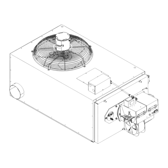
Operator's Manual: Models Saturn™ 140 & Saturn™ 230 "ALL THREAD" RODS BURNER MOUNTING BRACKET OBSERVATION LOUVERS CONNECTOR PORT BLOCK COMBUSTION SLEEVE INSTALLED IN CHAMBER I89086-A ON 2" X 2" BLOCKS Complete assembly of the furnace according to the following list of activities as illustrated above:... -
Page 23: Installing The Observation Port
Operator's Manual: Models Saturn™ 140 & Saturn™ 230 Installing the Observation Port CAUTION: To prevent serious personal injury, the observation port must be correctly installed according to the following procedure. A properly installed observation port permits safe observation of the flame during furnace operation. Be sure to follow all safety procedures as outlined in this manual when observing the flame through the port. - Page 24 Rotate the louvers to help direct the hot air away from the furnace. Figure 3C - Installing the Hot Air Discharge Louvers CAUTION: The Saturn™ 140 and Saturn™ 230 are Unit Heater furnaces ONLY. DO NOT install ductwork on these furnaces.
-
Page 25: Installing The Combustion Sleeve
Operator's Manual: Models Saturn™ 140 & Saturn™ 230 Installing the Combustion Sleeve Installing the Combustion Sleeve Inside the Combustion Chamber ATTENTION: DO NOT fire your furnace without the Combustion Sleeve in place, or poor flame retention will occur. Handle the Combustion Sleeve carefully to avoid damage. -
Page 26: Installing The Burner
Operator's Manual: Models Saturn™ 140 & Saturn™ 230 Installing the Burner Checking the Burner Nozzle and Electrodes NOTE: The burner nozzle is factory installed. Both furnace models use a Delavan 9-5 nozzle. The nozzle size is indicated on the nozzle as shown in Figure 3E. Refer also to Appendix A at the back of the manual for additional specifications/instructions on the burner nozzle. -
Page 27: Mounting The Burner On The Hinge Bracket
Operator's Manual: Models Saturn™ 140 & Saturn™ 230 Installing the Burner (continued) Mounting the Burner on the Hinge Bracket ATTENTION: Burner tube components (e.g. electrodes and retention head) are factory set. Handle the burner with extreme care so that burner components are not damaged. -
Page 28: Installing The Connector Block, Oil Line Tubing, And Air Line Tubing
Operator's Manual: Models Saturn™ 140 & Saturn™ 230 Installing the Connector Block, Oil Line Tubing, and Air Line Tubing ATTENTION: DO NOT use teflon tape on any fittings. Teflon tape residues will plug vital burner components and void your warranty. -
Page 29: Installing The Air Line Tubing
Operator's Manual: Models Saturn™ 140 & Saturn™ 230 Installing the Connector Block, Oil Line Tubing, and Air Line Tubing (continued) Installing the Air Line Tubing Remove and discard the red caps from the air line tubing. Push the air line tubing into the push fitting on the connector block until the tubing bottoms out in the fitting. - Page 30 Operator's Manual: Models Saturn™ 140 & Saturn™ 230 3-10...
-
Page 31: Section 4: Furnace Installation
Operator's Manual: Models Saturn™ 140 & Saturn™ 230 SECTION 4: FURNACE INSTALLATION Understanding Installation Installing your Clean Burn furnace is a multi-step process which includes: (1) Selecting a Location (6) Installing the Oil Lines (2) Mounting the Furnace (7) Installing the Compressed Air Line... - Page 32 S ection 4. These clearances also provide adequate space for servicing. Failure to maintain proper clearances may result in fire, explosion, personal injury, or death. Figure 4A - Typical Saturn™ 140 / 230 Furnace Installation...
-
Page 33: Selecting A Location
Operator's Manual: Models Saturn™ 140 & Saturn™ 230 Selecting a Location Guidelines for Selecting a Location The location you select for your furnace must allow the following: • Unobstructed, even heat distribution. • Safe, easy access for servicing. • Unobstructed passage for shop vehicles and equipment. -
Page 34: Mounting The Furnace
Operator's Manual: Models Saturn™ 140 & Saturn™ 230 Mounting the Furnace After selecting a safe and appropriate location for your furnace, construct the mounting system as required by the location and the following specifications. Ceiling Mounting WARNING: To prevent serious personal injury, ensure that your furnace mounting system can safely bear the suspended weight of the furnace and allow safe servicing of furnace components. -
Page 35: Raised Platform Mounting
Operator's Manual: Models Saturn™ 140 & Saturn™ 230 Mounting the Furnace (continued) Raised Platform Mounting WARNING: To prevent serious personal injury, make sure the platform is designed to safely bear the weight of the furnace and allow safe servicing of furnace components. The platform must be constructed of non-combustible materials (e.g. - Page 36 Operator's Manual: Models Saturn™ 140 & Saturn™ 230 Mounting the Furnace (continued) Floor Mounting (Continued) Figure 4E - Furnace Installed on a Mezanine With a Hot Air Outlet Diffuser...
-
Page 37: Oil Tank Installation Specifications
Operator's Manual: Models Saturn™ 140 & Saturn™ 230 Oil Tank Installation Specifications Ensure that your tank installation adheres to the following safety guidelines as stated here and in Section 1 of this manual. The tank safety label (shown at right) also summarizes these important specifications for tank installation and usage. -
Page 38: Installing The Tank Vent And Emergency Vent
Operator's Manual: Models Saturn™ 140 & Saturn™ 230 Oil Tank Installation Specifications (continued) TANK VENT KITS AVAILABLE FROM CLEAN BURN: CB Part # 70380 − 4" Tank Vent Kit (2) elbows (2) 6" nipples (1) mushroom cap vent PRESSURE (1) emergency vent... -
Page 39: Installing The Metering Pump
Operator's Manual: Models Saturn™ 140 & Saturn™ 230 Installing the Metering Pump Preparing for Installation Before starting installation of the metering pump, review Figures 4G, 4H, and 4I to become familiar with the metering pump components. You will also need to accomplish the following activities: •... - Page 40 Operator's Manual: Models Saturn™ 140 & Saturn™ 230 Figure 4H - Metering Pump Component Detail 4-10...
-
Page 41: Alternate Mounting: Horizontal Positioning
Operator's Manual: Models Saturn™ 140 & Saturn™ 230 Installing the Metering Pump (continued) Alternate Mounting: Horizontal Positioning ATTENTION: If the metering pump is to be mounted horizontally or on a bracket as shown in Figure 4I, the pump head must be rotated counterclockwise so that it is aligned in a horizontal position. The gauge arrow on the pump head must point up, or the pump will not prime. -
Page 42: Wiring The Furnace And Pump
Operator's Manual: Models Saturn™ 140 & Saturn™ 230 Wiring the Furnace and Pump WARNING: To avoid electrical shock, make sure that power to the furnace is turned OFF before connecting any wires. A licensed electrician should install all wiring to your furnace. All wiring must be in accordance with the National Uniform Electrical Code and local codes. -
Page 43: Installing The Suction Oil Line Components
Operator's Manual: Models Saturn™ 140 & Saturn™ 230 Installing the Suction Oil Line Components ATTENTION: It is critical that you adhere to the following specifications for suction oil line installation (oil line from the tank to the pump). If these specifications are not met, the metering pump will not function correctly and the burner will shut down on reset. - Page 44 Operator's Manual: Models Saturn™ 140 & Saturn™ 230 Installing the Suction Oil Line Components (continued) (1.) (e.) Prepare the canister filter for installation (continued): • Remove the plug from one of the 1/8" gauge ports in the canister filter and install the vacuum gauge.
- Page 45 Operator's Manual: Models Saturn™ 140 & Saturn™ 230 Install the suction oil line (from the the tank to the canister filter): a. Refer to Figures 4H and 4J. b. Prepare a piece of 1/2" O.D. copper tubing (user-supplied) which will function as the pick-up line from the tank to the canister filter.
-
Page 46: Installing The Pressure Relief Oil Line Back To The Tank
Operator's Manual: Models Saturn™ 140 & Saturn™ 230 Installing the Pressure Relief Oil Line Back to the Tank ATTENTION: It is critical that you adhere to the following specifications for plumbing the pressure relief back to the tank. The metering pump requires the installation of a pressure relief oil line back to the tank that you are pulling oil from as shown in Figures 4H, 4J, and 4K. -
Page 47: Installing The Pressure Oil Line Components
Operator's Manual: Models Saturn™ 140 & Saturn™ 230 Installing the Pressure Oil Line Components ATTENTION: It is critical that you adhere to the following specifications for pressure oil line installation (oil line from the pump to the furnace); if these specifications are not met, the metering pump will not function correctly and the burner will shut down on reset. -
Page 48: Installing The Stack
When designing your stack, adhere to the following specifications: • Models Saturn™ 140 and Saturn™ 230 require minimum 6" I.D. stack components. • Ensure that the vertical stack height is at least 10 feet PLUS one foot for every fitting (e.g. - Page 49 Operator's Manual: Models Saturn™ 140 & Saturn™ 230 Installing the Stack (continued) Figure 4L - Installation of "Class A" Stack Through Roof/Ceiling 4-19...
- Page 50 Operator's Manual: Models Saturn™ 140 & Saturn™ 230 Installing the Stack (continued) Figure 4M - Installation of "Class A" Stack Through Sidewall 4-20...
-
Page 51: Installing The Interior Stack
Operator's Manual: Models Saturn™ 140 & Saturn™ 230 Installing the Interior Stack WARNING: Single wall stack components may be used only for those portions of the stack which are located inside your building and away from any fire/burn hazards. Install the single wall stack with proper clearances from combustibles. Also ensure that the stack is located a safe distance from all shop personnel. -
Page 52: Installing The Stack Safety Switch For Canadian Installations
Operator's Manual: Models Saturn™ 140 & Saturn™ 230 Installing the Stack Safety Switch For Canadian Installations NOTE: CSA Standards require that all heating equipment must be installed with a stack safety switch. If your heating equipment is being installed in Canada, follow the instructions listed below. -
Page 53: Resetting The Stack Safety Switch
Operator's Manual: Models Saturn™ 140 & Saturn™ 230 Resetting the Stack Safety Switch WARNING: BURN HAZARD! To prevent serious personal injury, be sure to allow ample time, at least 30 minutes, for the stack, barometric damper, and switch to cool down before attempting to access and service these components. -
Page 54: Installing The Stack Penetration
Operator's Manual: Models Saturn™ 140 & Saturn™ 230 Installing the Stack Penetration WARNING: When running the stack through your ceiling, roof, or sidewall, you must use Class A/UL 103 HT double-wall insulated all-fuel stack components with a stainless steel liner. - Page 55 Operator's Manual: Models Saturn™ 140 & Saturn™ 230 Installing the Optional Draft Inducer (continued) NOTE: Lubricate the motor as recommended by the Draft Inducer manufacturer. Figure 4Q - Installation of the Optional Draft Inducer WARNING: Turn OFF the main power to the furnace before proceeding with the installation of the draft inducer.
-
Page 56: Installing The Wall Thermostat
Operator's Manual: Models Saturn™ 140 & Saturn™ 230 Installing the Optional Draft Inducer (continued) Refer to Figure 4Q. Follow the instructions included with the draft inducer to mount the draft inducer on the section of single-wall vertical stack. Position the draft plate all the way out so that it does not reduce the draft produced by the draft inducer. -
Page 57: Section 5: Metering Pump Priming
Operator's Manual: Models Saturn™ 140 & Saturn™ 230 SECTION 5: METERING PUMP PRIMING Understanding Metering Pump Priming Preparing your Clean Burn furnace for operation begins with priming the metering pump. The procedures in this section must be performed in sequence without interruption to properly prime the pump. -
Page 58: Priming The Metering Pump
Operator's Manual: Models Saturn™ 140 & Saturn™ 230 Priming the Metering Pump ATTENTION: The priming process must be done precisely as described in this procedure to ensure that all air is thoroughly bled from the system. Failure to bleed all air from the system will result in repeated burner shutdowns on reset. - Page 59 Priming the Metering Pump (continued) Activating the Pump NOTE: The Saturn™ 140 & Saturn™ 230 furnaces feature a priming switch which is mounted on the right-hand side of the electrical junction box on the front of the furnace cabinet. The priming switch has two positions: •...
-
Page 60: Vacuum Testing The Oil Pump
Operator's Manual: Models Saturn™ 140 & Saturn™ 230 Priming the Metering Pump (continued) Run the pump until a solid stream of oil flows from the pump bleeder. This will bleed all air out of the suction line, oil filter and pump head. - Page 61 Operator's Manual: Models Saturn™ 140 & Saturn™ 230 Vacuum Testing the Oil Pump (continued) If there are no suction leaks, the system will hold vacuum. NOTE: It is acceptable for the vacuum to drop one to five inches within one minute as the seal in the pump seats.
- Page 62 Operator's Manual: Models Saturn™ 140 & Saturn™ 230...
-
Page 63: Section 6: Starting And Adjusting The Burner
NOTE: The air gauge will not show any pressure until the burner starts. Before starting the burner for the first FIGURE 6A - Component Detail of the Saturn™ 125 Burner time, it is very important to turn the air regulator completely OFF as... -
Page 64: Starting The Burner
NOTE: The oil pressure is automatically adjusted by the metering pump. Initial Adjustments for the Saturn™ 140 Furnace Maximum Input = 140,000 BTUH @ 1.0 GPH with Saturn™ 125 Burner Oil Type Oil PSI / Flame Length... - Page 65 Operator's Manual: Models Saturn™ 140 & Saturn™ 230 Starting the Burner (continued) Observing the Flame Length: Visually inspect the flame length through the observation port. Refer to Figure 6B for an illustration of the desired flame length. The flame should extend no more than one-half of the way down the combustion chamber.
-
Page 66: Checking The Operation Of The Fan Motor
Operator's Manual: Models Saturn™ 140 & Saturn™ 230 Starting the Burner (continued) Checking for a Smokeless Burn: Check for a smokeless burn by observing the stack while the burner is running. If you see any smoke, repeat the previous steps for setting the combustion air band and adjusting the air regulator. -
Page 67: Section 7: Resetting The Oil Primary Control
SECTION 7: RESETTING THE OIL PRIMARY CONTROL Understanding the Oil Primary Control NOTE: The Saturn™ A2 primary controller (CB Part #33400) is a recycle type control, which features interrupted ignition operation. The oil primary control will go into safety lockout and shut the burner off when it detects flame-out during burner operation. -
Page 68: The Blower/Fan Switch
Operator's Manual: Models Saturn™ 140 & Saturn™ 230 The Blower/Fan Switch The Saturn™ 140 & Saturn™ 230 furnaces feature an F-180 blower/fan switch (normally open) which is surface mounted at the front of the combustion chamber (see Figure 7B). The blower/fan switch senses the temperature of the combustion chamber as the burner is firing. - Page 69 Operator's Manual: Models Saturn™ 140 & Saturn™ 230 The Hi-Temp Limit Switches (continued) Figure 7B - Locating the Hi-Temp Limit Switches...
- Page 70 Operator's Manual: Models Saturn™ 140 & Saturn™ 230...
-
Page 71: Section 8: Adjusting The Draft Over Fire
Operator's Manual: Models Saturn™ 140 & Saturn™ 230 SECTION 8: ADJUSTING THE DRAFT OVER FIRE Understanding the Importance of Draft Draft in the furnace is created as the hot combustion gases rise up the stack, creating a negative pressure inside the stack and the furnace. This negative pressure is measured as inches of water column (W.C.) of draft. -
Page 72: Adjusting The Barometric Damper
Operator's Manual: Models Saturn™ 140 & Saturn™ 230 Adjusting the Barometric Damper NOTE: If the draft over fire is not in the -.02 to -.04 w.c. range, it is necessary to adjust the barometric damper. Before starting the burner, turn the weight on the flapper COUNTERCLOCKWISE until the flapper remains closed. -
Page 73: Understanding The Effect Of Exhaust Fans On Draft
Operator's Manual: Models Saturn™ 140 & Saturn™ 230 Understanding the Effect of Exhaust Fans on Draft Any type of exhaust fan, paint booth, or exhaust system in a building will create negative pressure in the building unless there is a source of make-up air (i.e. fresh air which enters the building and replaces the air removed by the exhaust fans.) Refer to Figure 8C on the following page. - Page 74 Operator's Manual: Models Saturn™ 140 & Saturn™ 230 Figure 8C - Proper Draft vs. Backdraft...
-
Page 75: Installing A Make-Up Air Louver
Operator's Manual: Models Saturn™ 140 & Saturn™ 230 Installing a Make-up Air Louver Exhaust Fans and Make-up Air Louvers When exhaust fans are operated in tight buildings, there is little or no source of fresh air to replace the air removed from the building by the exhaust fan. This results in negative pressure (vacuum) in the building which creates severe backdraft problems at the furnace. - Page 76 Operator's Manual: Models Saturn™ 140 & Saturn™ 230 Installing a Make-up Air Louver (continued) Calculated Opening Size Required Louver / Grill Size (Square Feet) (Inches) From 0.000 to 0.569 10 x 10 From 0.570 to 0.900 12 x 12 From 0.901 to 1.556 16 x 16 From 1.557 to 2.070...
-
Page 77: Section 9: Maintenance
Operator's Manual: Models Saturn™ 140 & Saturn™ 230 SECTION 9: MAINTENANCE Understanding Maintenance Servicing your Clean Burn furnace in a timely manner is very important to keep your furnace running in peak condition. Just as an automobile requires periodic maintenance such as oil changes, engine tune-ups, etc. your Clean Burn furnace also requires regularly scheduled service. -
Page 78: Cleaning The Canister Filter
Operator's Manual: Models Saturn™ 140 & Saturn™ 230 Periodic Burner Inspection (continued) • Check the air pressure by observing the air gauge; proper air pressure settings are provided in Section 6. DO NOT over fire the burner; doing so on a continual basis will damage the furnace. -
Page 79: Servicing The Metering Pump
Operator's Manual: Models Saturn™ 140 & Saturn™ 230 Servicing the Metering Pump Refer to Figure 9B. Remove the pump head cover (part 1). Remove the screen (part 2) and wash it. Remove and discard the used gasket (part 3). Install a new gasket (Clean Burn Part #32422). -
Page 80: Cleaning The Tank
Operator's Manual: Models Saturn™ 140 & Saturn™ 230 TO BURNER METERING PUMP FUNNEL WITH BALL VALVE VENT SUCTION OIL LINE EMERGENCY VENT OIL STORAGE TANK CLEANOUT CHECK VALVE CHECK VALVE SCREEN 12" I88670−F Figure 9C - Check Valve Detail Cleaning the Tank DO NOT allow water, sludge, or other debris to accumulate in your oil supply tank to the point that non- combustible or harmful materials are drawn into the pump or burner. -
Page 81: Cleaning Ash From The Furnace
Operator's Manual: Models Saturn™ 140 & Saturn™ 230 Cleaning Ash from the Furnace NOTE: The maintenance interval for cleaning ash from the furnace is 800 to 1000 hours of operation as indicated on the hour meter on the pump (refer to the servicing intervals at the beginning of this chapter). Be sure to clean the ash from your furnace at least twice during the heating season. - Page 82 Operator's Manual: Models Saturn™ 140 & Saturn™ 230 Cleaning the Ash (continued) Ensure that power has been turned OFF, and all "hot" components have been allowed to cool sufficiently. (Allow at least one hour for the Combustion Sleeve to cool.) Clean the ash from the stack components: a.
-
Page 83: Annual Burner Tune-Up
Operator's Manual: Models Saturn™ 140 & Saturn™ 230 Cleaning the Ash (continued) k. Re-install the furnace components: Swing the clean-out door shut; install and tighten the lock-down nuts so that the door seals properly. Re-install the air and oil lines on the bottom of the connector block. - Page 84 Operator's Manual: Models Saturn™ 140 & Saturn™ 230...
-
Page 85: Section 10: Troubleshooting
Operator's Manual: Models Saturn™ 140 & Saturn™ 230 SECTION 10: TROUBLESHOOTING The following charts and tables are provided for reference in troubleshooting any difficulties encountered in furnace operation and adjustment. • The Flow Chart outlines the proper sequence of events in furnace operation -- use this chart to help diagnose where a problem may be occurring. - Page 86 Operator's Manual: Models Saturn™ 140 & Saturn™ 230 10-2...
- Page 87 Operator's Manual: Models Saturn™ 140 & Saturn™ 230 PROBLEM POSSIBLE CAUSE POSSIBLE ACTION(S) Burne r won’ t run at a ll and Circuit b re aker/ma in switch ope n. Close circuit b re aker/switch . Gre en power light is NOT ON.
- Page 88 Operator's Manual: Models Saturn™ 140 & Saturn™ 230 PROBLEM POSSIBLE CAUSE POSSIBLE ACTION(S) Burner ignites, but will not stay running There is a fuel delivery problem. Follow the procedures listed in the and Burner shuts off on reset within 15 next problem.
- Page 89 Operator's Manual: Models Saturn™ 140 & Saturn™ 230 PROBLEM POSSIBLE CAUSE POSSIBLE ACTION(S) Burner ignites and Burner shuts off on There is air in the fuel supply. Prime the pump. If the pump will reset sometime later during the day or not prime or there is air in the oil night.
- Page 90 Operator's Manual: Models Saturn™ 140 & Saturn™ 230 PROBLEM POSSIBLE CAUSE POSSIBLE ACTION(S) Pump will not prime and Pump motor is There is a leak(s) in the suction Follow the specifications in running. line. Section 4 to make sure the...
- Page 91 Operator's Manual: Models Saturn™ 140 & Saturn™ 230 PROBLEM POSSIBLE CAUSE POSSIBLE ACTION(S) Pump will not prime and Pump motor is There is NO power on the Start the burner and adjust the air NOT running. pump circuit from the burner.
- Page 92 Operator's Manual: Models Saturn™ 140 & Saturn™ 230 10-8...
-
Page 93: Detailed Furnace Specifications
Operator's Manual: Models Saturn™ 140 & Saturn™ 230 APPENDIX A Detailed Furnace Specifications Furnace Model Saturn Saturn BTUH Input 140,000* 230,000* @ 1.0 GPH @ 1.6 GPH Listed Fuels: #2 Fuel Oil #2 Fuel Oil #4 and #5 Fuel Oils (U.S.) #4 and #5 Fuel Oils (U.S.) -
Page 94: Burner Technical Specifications
Operator's Manual: Models Saturn™ 140 & Saturn™ 230 Burner Technical Specifications Saturn Burner Ignition Transformer Carlin Transformer 14,000 Volts Nozzle Delavan 9-5 Burner Motor 1/10 HP 3200 RPM with centrifugal switch Burner Motor Rotation CCW shaft end Compressed Air Requirements 2.5 CFM @ 30 psi... - Page 95 Operator's Manual: Models Saturn™ 140 & Saturn™ 230 Saturn™ 140 Dimensions 9.5" 39.25" 6.62" 26" 20" 47.25" 10.38 MOUNTING HOLE DIMENSIONS 32" 29.5" I89105-A 28" Saturn™ 230 Dimensions 10" 46.5" 7.38 23" 27.25" 54.6" 10.38 MOUNTING HOLE DIMENSIONS 33" 35"...
-
Page 96: Burner Components
Operator's Manual: Models Saturn™ 140 & Saturn™ 230 Burner Components 16 15 14 I89137 FIGURE A1 - Burner Component Detail... - Page 97 Operator's Manual: Models Saturn™ 140 & Saturn™ 230 Burner Components (continued) ITEM# PART# DESCRIPTION 26136 COVER LH 125 26135 COVER RH 125 33247 TERMINAL BLOCK 14088 CONNECTOR RECEPTACLE 11308 RETENTION HEAD 26078 LID TAB 11633 HOUSING SATURN 125 A. 33400...
- Page 98 Operator's Manual: Models Saturn™ 140 & Saturn™ 230 Burner Components (continued) FIGURE A2 - Preheater Block Assembly Component Detail...
- Page 99 Operator's Manual: Models Saturn™ 140 & Saturn™ 230 Burner Components (continued) ITEM# PART# DESCRIPTION 32000 NOZZLE 9-5 34436 MS Pan HD 10-32X5/8Z 26134 SUPPORT NOZZLE HOLDER 26140 GUIDE 32199 PLUG,HEX SOC, 1/16 NPT 33455 TEMPATURE SWITCH L-150 33041 PROVING SWITCH 120D N.O.
- Page 100 Operator's Manual: Models Saturn™ 140 & Saturn™ 230 Burner Components (continued) BURNER NOZZLE NOZZLE IS STAMPED EITHER 9−5 OR −5 ON FLAT OF NOZZLE HEAD SIDE VIEW − AA 3/16" GAP BETWEEN ELECTRODES & NOZZLE CRITICAL DIMENSIONS: ELECTRODES MUST BE FLUSH WITH NOZZLE TIP.
-
Page 101: Removing The Nozzle For Cleaning
Operator's Manual: Models Saturn™ 140 & Saturn™ 230 Burner Components (continued) DISTRIBUTOR STEM HEAD Model Nozzle Size Saturn™ A2 Delavan 9-5 NOZZLE SIZE IS STAMPED ON FLAT OF NOZZLE HEAD ORIFICE O−RING I88378 Removing the Nozzle for Cleaning: Remove the lock-down nut on the mounting flange bolt. - Page 102 Operator's Manual: Models Saturn™ 140 & Saturn™ 230 Saturn™ 140 Cabinet SATURN 140 DETAIL B DETAIL A (OPTIONAL) I89107-A A-10...
- Page 103 Operator's Manual: Models Saturn™ 140 & Saturn™ 230 Item # Part # Description 29145 SHROUD TOP 140 29144 SHROUD REAR 140 70479 DUCT CAP 6" 24 GA GALV 29146 BREECH 6" 23093 FLUE TUBE 3X33.75 34191 3/8-16 X 3/4 CARRIAGE BOLT...
- Page 104 Operator's Manual: Models Saturn™ 140 & Saturn™ 230 Saturn™ 230 Cabinet SATURN 230 DETAIL B DETAIL A 5 (OPTIONAL) I89108 A-12...
- Page 105 Operator's Manual: Models Saturn™ 140 & Saturn™ 230 Item # Part # Description 70479 DUCT CAP 6" 24 GA GALV 29146 BREECH 6" 21102 FLUE TUBE 3X41 29189 LOUVER 230 90245 AIR DISCHARGE HOODE 230 A 34118 5/16-18 X 3/4 HEX WASHER HEAD...
-
Page 106: Metering Pump Components
Operator's Manual: Models Saturn™ 140 & Saturn™ 230 Metering Pump Components SUPPLY RETURN TO BURNER TO TANK PACKAGED WITH CLEAN BURN EQUIPMENT SINGLE PIECE OF COPPER TUBING (USER SUPPLIED) PACKAGED WITH CLEAN BURN EQUIPMENT A-14... - Page 107 Operator's Manual: Models Saturn™ 140 & Saturn™ 230 ITEM# PART# DESCRIPTION 33363 CAPACITOR 33291 GEAR MOTOR SATURN 33293 GEAR MOTOR SATURN 11322 MOUNT METER PUMP A 32037 1/8 NPT X 1/4 TUBE COMPRESSION FITTING 1/4 COPPER OR ALUMINUM TUBING 3/8 OR 1/2 TUBE FLARE NUT...
- Page 108 Operator's Manual: Models Saturn™ 140 & Saturn™ 230 A-16...
-
Page 109: Wiring Diagrams
Operator's Manual: Models Saturn™ 140 & Saturn™ 230 APPENDIX B Wiring Diagrams... - Page 110 Operator's Manual: Models Saturn™ 140 & Saturn™ 230 Wiring Diagrams (continued) FIGURE B2 - Saturn™ A2 Burner Wiring Diagram...
-
Page 111: Ladder Schematic
5-12-11 N.M .S. B LOCK TEM P. SW ITCH TW O 140 W A TTS B LOCK HEATERS 150° POW ER O N FIGURE B3 - Ladder Schematic for Saturn™ 140/230 with Saturn™ A2 Burner (120 Volts / 60 Hz) -
Page 112: Metering Pump Wiring Schematic
Operator's Manual: Models Saturn™ 140 & Saturn™ 230 Wiring Diagrams (continued) ENCLOSED J−BOX GROUND BLUE L 2 (WHT) L 1 (BLK) * 115 V 60 HZ POWER FROM OIL PUMP CIRCUIT SEE FURNACE SCHEMATIC 42533 Figure B4 - Metering Pump Wiring Schematic... -
Page 113: Furnace Service Record
Operator's Manual: Models Saturn™ 140 & Saturn™ 230 APPENDIX C Furnace Service Record Furnace Purchased: Date __________ From (name/phone) _______________________________ Furnace Installed: Date __________ By (name/phone)__________________________________ Furnace Inspected: Date __________ By (name/phone)__________________________________ Note: Refer to Section 9 for Maintenance Instructions... - Page 114 Operator's Manual: Models Saturn™ 140 & Saturn™ 230...
Need help?
Do you have a question about the 140 and is the answer not in the manual?
Questions and answers