
Related Manuals for Durr Technik KK70


Summary of Contents for Durr Technik KK70
- Page 1 Oil-free piston compressors KK and piston vacuum pumps KV Installation and Operating Instructions 0678106030L02 ...
-
Page 3: Table Of Contents
9�1 Maintenance plan � � � � � � � � � � � � � � 78 4�2 Piston vacuum pump of series KV8 � 25 4�3 Piston compressor of series KK15 � � 29 4�4 Piston vacuum pump of series KV15 �... -
Page 4: Important Information
Important information 1 Documentation The signal word differentiates between different levels of danger: These assembly and operating instructions form – DANGER an integral part of the unit� They correspond to High risk of danger of serious injury or death the particular model of the unit and to the tech- –... -
Page 5: Safety
Important information 2 Safety 2.3 General safety notes • Before using the unit observe any and all Dürr Technik has designed and developed the guidelines, laws, regulations and other restric- unit in such a way that danger is to a large ex- tions which may apply to the unit�... -
Page 6: 2�7 Transportation And Storage
Important information 2.7 Transportation and storage 2.8 Disposal The unit is shipped in a cardboard box filled with Unit packaging padding� This packaging ensures Dispose of the unit properly according that the unit is optimally protected in transit� As to valid state and local legislation� far as possible, always use the original packag- ing for transporting or storing the unit�... -
Page 7: Product Description
3 Overview 3.1 Delivery Contents Oil-free piston compressors KK Modular structure Oil-free piston compressors of series KK8, KK15, KK40 and KK70 each consisting of a compressor head with an electric motor� The following electric motors are available: Type A Single-phase AC motors Type B... -
Page 8: 3�2 Spare Parts And Accessories
Product description 3.2 Spare parts and accessories Oil-free piston compressors and piston vacuum pumps of series KK8 / KV8 Figure 1: Oil-free piston compressors and piston vacuum pumps KK8 / KV8 with item numbers for spare parts 0678106030L02 1411V002... - Page 9 Product description Spare parts KK8 Type A-025 A-025 D-030 D-030 Article no. 0536 1030 0536 1130 0825-02 0825-03 Item no. Crankcase cover 0825-119- 0825-119- 0825-119- 0825-119- Cylinder head 0825-111- 0825-111- 0825-111- 0825-111- Lamellar valve 2 x 0825- 2 x 0825- 2 x 0825- 2 x 0825- 118-01 118-01 118-01 118-01...
- Page 10 Product description Spare parts KV8 Type A-025E A-025E D-030E D-030E Article no. 0536 2030 0536 2130 0826-02 0826-03 Item no. Crankcase cover 0825-119- 0825-119- 0825-119- 0825-119- Cylinder head 0825-111- 0825-111- 0825-111- 0825-111- Lamellar valve 2 x 0825- 2 x 0825- 2 x 0825- 2 x 0825- 118-01 118-01 118-01 118-01...
- Page 11 Product description Oil-free piston compressors and piston vacuum pumps of series KK15 / KV15 Figure 2: Oil-free piston compressors and piston vacuum pumps KK15 / KV15 with item numbers for spare parts 0678106030L02 1411V002...
- Page 12 Product description Spare parts KK15 Type A-038 A-038 A-038 Article no. 0574 1030 0574 1130 0835-73.. Item no. Crankcase cover 0832-119-02 0832-119-02 0832-119-02 Cylinder head 0833-111-02 0833-111-02 0833-111-02 Lamellar valve 2 x 0832-118- 2 x 0832-118- 2 x 0832-118- Valve plate 0832-115-01 0832-115-01 0832-115-01 Crank with connecting rod 4, 15 0832-241-51...
- Page 13 Product description Type A-061 B-061 Article no. 0835-74 0575 1000 Item no. Crankcase cover 0832-119-02 0832-119-02 Cylinder head 0833-111-02 0833-111-02 Lamellar valve 2 x 0832-118-01 2 x 0832-118-01 Valve plate 0832-115-01 0832-115-01 Crank with connecting rod 4, 15 0832-241-51 0832-241-51 Spare parts kit: cup seal / cylinder 6, 9, 10, 12, 14 0832-981-00 0832-981-00 Vibration dampers 0835-991-00 (33 0835-991-00 (33 Shore) Shore)
- Page 14 Product description Spare parts KV15 Type A-038E D-040E D-040E A-062E1 Article no. 0839-43 0839-22 0839-25 0837-21A Item no. Crankcase cover 0832-119- 0832-119- 0832-119- 2 x 0832- 119-02 Cylinder head 0833-111- 0833-111- 0833-111- 2 x 0833- 111-04 Lamellar valve 2 x 0832- 2 x 0832- 2 x 0832- 4 x 0832- 118-01 118-01...
- Page 15 Product description Oil-free piston compressors and piston vacuum pumps of series KK40 / KV40 Figure 3: Oil-free piston compressors and piston vacuum pumps KK40 / KV40 with item numbers for spare parts 0678106030L02 1411V002...
- Page 16 Product description Spare parts KK40 Type A-065 A-065 B-065 Article no. 0431 1100 0431 1400 0431 1300 Item no. Crankcase cover 0431 0090 0431 0090 0431 0090 Cylinder head 2 connections 0833-111-12 0833-111-12 0833-111-12 Cylinder head 4 connections Valve plate 0832-115-50 0832-115-50 0832-115-50 Spare parts kit: cup seal / 6, 9, 10, 12, cylinder 0431 0902 0431 0902 0431 0902 Vibration damper set 0880-991-00...
- Page 17 Product description Spare parts KV40 Type AG-065-2E AG-132E Article no. 0431 3100 0431 4400 Item no. Crankcase cover 0431 0091 0431 0091 Cylinder head 2 connections 0832-111-12 0832-111-12 Cylinder head 4 connections 0833-111-13 0833-111-13 Valve plate 2 x 0832-115-50 2 x 0832-115-50 Crank with connecting rod Spare parts kit: cup seal / cylinder 6, 9, 10, 12, 14 2 x 0431 0904 2 x 0431 0904 Vibration damper set 0880-991-00...
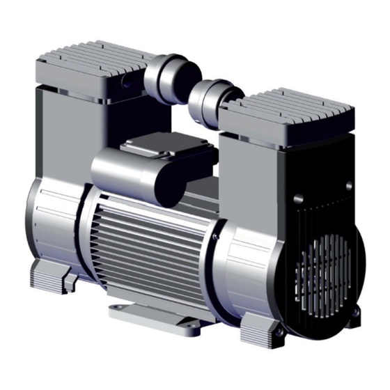
- Page 18 Product description Oil-free piston compressors and piston vacuum pumps of series KK70 Figure 4: Oil-free piston compressors and piston vacuum pumps KK70 with item numbers for spare parts 0678106030L02 1411V002...
- Page 19 Product description Spare parts KK70 Type A-100 A-100 B-100 Article no. 0880-03 0880-04 0880-05 Item no. Crankcase cover 0880-119-01 0880-119-01 0880-119-01 Cylinder head 0880-290-01 0880-290-01 0880-290-01 Valve plate + lamellar valve 0880-280-01 0880-280-01 0880-280-01 Seal (cylinder) 0880-114-02 0880-114-02 0880-114-02 Seal (valves) 2 x 0880-121- 2 x 0880-121- 2 x 0880-121- Spare parts kit: cup seal and cylinder 10, 14...
- Page 20 Product description Type A-200 B-200 Article no. 0881-01 0881-05 Item no. Crankcase cover 2 x 0880-119-01 0880-119-01 Cylinder head 2 x 0880-290-01 0880-290-01 Valve plate + lamellar valve 2 x 0880-280-01 0880-280-01 Seal (cylinder) 2 x 0880-114-02 0880-114-02 Seal (valves) 4 x 0880-121-01 2 x 0880-121-01 Spare parts kit: cup seal and cylinder 10, 14 2 x 0880-981-00 2 x 0880-981-00 Spare parts kit: Crank with piston,...
- Page 21 Product description Piston compressors KK accessories Piston com- KK15 KK40 KK70 pressors Designation G1/8" G1/4" G1/4" G1/4" Air intake filter single G1/8" 9000-416-01 Air intake filter single G1/4" 9000-416-16 9000-416-16 9000-416-16 Air intake filter 9000-416- 9000-416- 9000-416- 9000-416- standard 0030** 0030 0030 0030 not shown...
- Page 22 Product description Accessories for piston vacuum pumps KV Piston vacuum KV15 KV40 pumps Designation G1/8" G1/4" G1/4" Silencer G1/4“ ex- ternal thread 0837-001-00** 0837-001-00 0837-001-00 Filter with non-re- turn valve (kit of 3) 1100-040-00 1100-040-00 1100-040-00 * Applies to piston vacuum pumps starting from year of manufacture 02/2006 **requires reduction nipple 9000-310-57 Capacitors on request�...
-
Page 23: Technical Data
Product description 4 Technical data 4.1 Piston compressor of series KK8 Schematic drawing KK8/KV8 G1/8" Figure 5: KK8 / KV8; Type: A-025; A-025E G1/8" 47,5 Figure 6: KK8 / KV8; Type: D-030; D-030E 0678106030L02 1411V002... - Page 24 Product description Technical Data KK8 Type A-025 Electrical data Type A-025 A-025 Article no. 0536 1030 0536 1130 Mains frequency Nominal voltage 110/115 110/115 Rated output P1 (W) Rated current 1�7 1�8 1�2 Rotational speed 1400 1660 1400 1600 Duty cycle 100% 100% 100% 100% Type of protection General technical data Delivery volume 0 bar l/min Rated pressure Safety pressure PS Sound pressure level dB(A) Weight 4�8...
- Page 25 Product description Type D-030 Electrical data Type D-030 D-030 Article no. 0825-02 0825-03 Mains frequency Nominal voltage 12 VDC 24 VDC Rated output P1 (W) Rated current 6�4 Rotational speed 1500 1570 Duty cycle 100% 100% Type of protection General technical data Delivery volume 0 bar l/min Rated pressure Safety pressure PS Sound pressure level dB(A) Weight 4�4 4�4 Dimensions (l x w x h) 209 x 108 x 156 209 x 108 x 156 Remarks...
- Page 26 Product description Performance diagram KK8 D-030 A-025 Pressure p [bar] Figure 7: Delivery volume at 50 Hz (60 Hz approx. +18%) 0678106030L02 1411V002...
-
Page 27: 4�2 Piston Vacuum Pump Of Series Kv8
Product description 4.2 Piston vacuum pump of series KV8 Schematic drawing KK8/KV8 G1/8" Figure 8: KK8 / KV8; Type: A-025; A-025E G1/8" 47,5 Figure 9: KK8 / KV8; Type: D-030; D-030E 0678106030L02 1411V002... - Page 28 Product description Technical data KV8 Type A-025E Electrical data Type A-025E A-025E Article no. 0536 2030 0536 2130 Mains frequency Nominal voltage 110/115 110/115 Rated output P1 (W) Rated current 1�64 1�5 0�7 0�9 Rotational speed 1300 1600 1450 1720 Duty cycle 100% 100% 100% 100% Type of protection General technical data Suction capacity S l/min End pressure P mbar <150 <150 <150...
- Page 29 Product description Type D-030E Electrical data Type D-030E D-030E Article no. 0826-02 0826-03 Mains frequency Nominal voltage 12 VDC 24 VDC Rated output P1 (W) Rated current 6�7 Rotational speed 1750 1700 Duty cycle 100% 100% Type of protection General technical data Suction capacity S l/min End pressure P mbar <180 <180 Sound pressure level dB(A) Weight 4�4 4�4 Dimensions (l x w x h) 209 x 108 x 156...
- Page 30 Product description Performance diagram KV8 D-030E A-025E 1000 Pressure p [mbar] Figure 10: Suction capacity based on atmospheric pressure at 50 Hz (60 Hz approx. + 18%) 1000 A-025E D-030E 1000 Pump-down time [s] Figure 11: Pump down time for a 10-l volume at 50 Hz 0678106030L02 1411V002...
-
Page 31: 4�3 Piston Compressor Of Series Kk15
Product description 4.3 Piston compressor of series KK15 Schematic drawing KK15/KV15 G1/4" Figure 12: KK15 / KV15, Type: A-038; B-038; A-061; B-061 G1/4" Figure 13: KK15 / KV15; Type: A-062 0678106030L02 1411V002... - Page 32 Product description G1/4" G1/8" Figure 14: KK15; Type: A-035/62 0678106030L02 1411V002...
- Page 33 Product description Technical data KK15 Type A-035/62; A-038 Electrical data Type A-035/62 A-038 Article no. 0841-29 0835-73.. Mains frequency Nominal voltage Rated output P1 (W) Rated current 1�7 1�6 1�5 1�5 Rotational speed 1385 1650 1300 1500 Duty cycle 100% 100% 100% 100% Type of protection General technical data Delivery volume 0 bar l/min Rated pressure Safety pressure PS Sound pressure level...
- Page 34 Product description Type A-038 Electrical data Type A-038 A-038 Article no. 0835-49 0602 1030 Mains frequency Nominal voltage 100-110 100-127 Rated output P1 (W) 270-300 280-350 Rated current 3�2-3�5 2�8-3�1 1�5 1�5 Rotational speed 1380 1650-1700 1300 1500 Duty cycle 100% 100% 100% 100% Type of protection General technical data Delivery volume 0 bar l/min Rated pressure Safety pressure PS Sound pressure level dB(A)
- Page 35 Product description Type A-038 Electrical data Type A-038 Article no. 0574 1030 Mains frequency Nominal voltage 115* 115* Rated output P1 (W) Rated current 4�1 3�2 2�1 1�9 Rotational speed 1370 1630 1370 1630 Duty cycle 100% 100% 100% 100% Type of protection General technical data Delivery volume 0 bar l/min Rated pressure Safety pressure PS Sound pressure level dB(A) Weight 7�5 7�5 7�5...
- Page 36 Product description Type A-038 Electrical data Type A-038 Article no. 0574 1130 Mains frequency Nominal voltage 230* 230* Rated output P1 (W) Rated current 2�1 1�9 4�1 3�2 Rotational speed 1370 1630 1370 1630 Duty cycle 100% 100% 100% 100% Type of protection General technical data Delivery volume 0 bar l/min Rated pressure Safety pressure PS Sound pressure level dB(A) Weight 7�5 7�5 7�5...
- Page 37 Product description Type B-038; D-040 Electrical data Type B-038 D-040 D-040 Article no. 0835-75.. 0832-25 0832-22.. Mains frequency Nominal voltage 3 ph� 400 3 ph� 400 12 VDC 24 VDC Rated output P1 (W) Rated current 0�9 0�8 17�5 Rotational speed 1400 1670 1600 1800 Duty cycle 100% 100% 100% 100%...
- Page 38 Product description Type A-061; B-061 Electrical data Type A-061 B-061 Article no. 0835-74.. 0575 1000 Mains frequency Nominal voltage 3 ph� 400 3 ph� 400 Rated output P1 (W) Rated current 2�9 2�7 0�9 0�9 Rotational speed 2680 3130 2740 3200 Duty cycle 100% 100% 100% 100% Type of protection General technical data Delivery volume 0 bar l/min Rated pressure...
- Page 39 Product description Type D-061; A-062 Electrical data Type D-061 D-061 D-061 A-062 Article no. 0361 1000 0513 1000 0835-46 0834-23.. Mains frequency Nominal voltage 110 VDC 24 VDC 12 VDC Rated output P1 (W) Rated current 3�7 Rotational speed 2610 2900 2400 1390 Duty cycle S3 30 min S3 10 min 100% 100% Type of protection...
- Page 40 Product description Type A-062; B-062 Electrical data Type A-062 A-062 B-062 Article no. 0834-27 0833-36 0834-13 Mains frequency Nominal voltage 3 ph� 380- 3 ph� 460- Rated output P1 (W) Rated current 2�4 5�3 0�9 0�9 Rotational speed 1660 1620 1315 1635 Duty cycle 100% 100% 100% 100% Type of protection 00 / 20* General technical data...
- Page 41 Product description Performance diagram KK15 A-062 / B-062 A-061 / B-061 / D-061 A-038 / B-038 / D-040 A-035/62 Pressure p [bar] Figure 15: Delivery volume at 50 Hz (60 Hz approx. +18%) 0678106030L02 1411V002...
-
Page 42: Kv15
Product description 4.4 Piston vacuum pump of series KV15 Schematic drawing KK15/KV15 G1/4" Figure 16: KK15 / KV15, Type: A-038; B-038; A-061; B-061 G1/4" Figure 17: KK15 / KV15; Type: A-062 0678106030L02 1411V002... - Page 43 Product description G1/4" Figure 18: KK15 / KV15; Type: D-040; D-040E; D-061E 0678106030L02 1411V002...
- Page 44 Product description Technical data KV15 Typ A-038E Electrical data Type A-038E Article no. 0839-73 Mains frequency Nominal voltage Rated output P1 (W) Rated current 1�3 Rotational speed 1440 1710 Duty cycle 100% 100% Type of protection General technical data Suction capacity S l/min End pressure P mbar Sound pressure level dB(A) Weight 6�4 6�4 Dimensions (l x w x h) 249 x 156 x 180 249 x 156 x 180 Dimensions (x; y) 80;...
- Page 45 Product description Typ D-040E; B-061E Electrical data Type D-040E (12V) D-040E (24V) B-061E Article no. 0839-25 0839-22 0575 1100 Mains frequency Nominal voltage 12 VDC 24 VDC 3 ph� 400 3 ph� 400 Rated output P1 (W) Rated current 8�7 0�9 0�9 Rotational speed 1800 2000 2740 3200 Duty cycle 100% 100% 100% 100%...
- Page 46 Product description Type D-061E (24V) Electrical data Type D-061E (24V) Article no. 0513 1100 Mains frequency Nominal voltage 24 VDC Rated output P1 (W) Rated current Rotational speed 2950 Duty cycle 100% Type of protection General technical data Suction capacity S l/min End pressure P mbar Sound pressure level dB(A) Weight 7�1 Dimensions (l x w x h) 234 x 137 x 190 Dimensions (x; y) 90; 112 Remarks Ambient conditions for operation Temperature...
- Page 47 Product description Type A-062E2; A-062E1 Electrical data Type A-062E2 A-062E1 Article no. 0838-21A 0837-21A Mains frequency Nominal voltage Rated output P1 (W) Rated current 1�2 1�7 1�6 1�2 Rotational speed 1360 1620 1410 1630 Duty cycle 100% 100% 100% 100% Type of protection General technical data Suction capacity S l/min End pressure P mbar Sound pressure level dB(A) Weight 9�3 9�3...
- Page 48 Product description Performance diagram KV15 A-062E2 B-061E / D-061E A-062E1 A-038E / D-040E 1000 Pressure p [mbar] Figure 21: Suction capacity based on atmospheric pressure at 50 Hz (60 Hz approx. + 18%) 1000 A-062E2 B-061E / D-061E A-062E1 A-038E / D-040E 1000 Pump-down time [s] Figure 22: Pump down time for a 10-l volume at 50 Hz...
-
Page 49: 4�5 Piston Compressor Of Series Kk40
Product description 4.5 Piston compressor of series KK40 Schematic drawing KK40/KV40 G1/4" Figure 23: KK40 / KV40; Type: A-065; B-065; A-065E G1/4" Figure 24: KK40 / KV40; Type: AG-132; BG-132; AG-065-2E; A-065E; AG-132E; BG-132E 0678106030L02 1411V002... - Page 50 Product description G1/4" Figure 25: KK40 / KV40; Type: D-075 G1/4" Figure 26: KK40; Type: DG-160 0678106030L02 1411V002...
- Page 51 Product description Technical data KK40 Type A-065; B-065 Electrical data Type A-065 B-065 Article no. 0431 1100 0431 1300 Mains frequency Nominal voltage 3 ph� 400 3 ph� 400 Rated output P1 (W) Rated current 2�5 2�6 1�1 1�1 Rotational speed 1350 1600 1440 1710 Duty cycle 100% 100% 100% 100% Type of protection General technical data Delivery volume 0 bar l/min...
- Page 52 Product description Type A-065; D-075 Electrical data Type A-065 D-075 Article no. 0431 1400 0692 1000 Mains frequency Nominal voltage 110/115 110/115 24 VDC Rated output P1 (W) Rated current 5�1 5�3 Rotational speed 1400 1650 1800 Duty cycle 100% 100% 100% Type of protection General technical data Delivery volume 0 bar l/min Rated pressure Safety pressure PS Sound pressure level dB(A) Weight 14�4 14�4...
- Page 53 Product description Type AG-132 Electrical data Type AG-132 AG-132 Article no. 0431 2200 0431 2300 Mains frequency Nominal voltage 110/115 Rated output P1 (W) 1000 Rated current 3�9 4�1 9�3* Rotational speed 1380 1630 1700 Duty cycle 100% 100% 100% Type of protection General technical data Delivery volume 0 bar l/min Rated pressure Safety pressure PS Sound pressure level dB(A) Weight Dimensions (l x w x h) 340 x 276 x 340 x 276 x 340 x 276 x...
- Page 54 Product description Type BG-132; DG-160 Electrical data Type BG-132 DG-160 Article no. 0431 2500 0571 3000C Mains frequency Nominal voltage 3 ph� 400 3 ph� 400 24 VDC Rated output P1 (W) Rated current 1�8 Rotational speed 1440 1700 1850 Duty cycle 100% 100% 100% Type of protection General technical data Delivery volume 0 bar l/min Rated pressure Safety pressure PS Sound pressure level dB(A)
- Page 55 Product description Performance diagram KK40 DG-160 AG-132 / BG-132 D-075 A-065 / B-065 Pressure p [bar] Figure 27: Delivery volume at 50 Hz (60 Hz approx. +18%) 0678106030L02 1411V002...
-
Page 56: Kv40
Product description 4.6 Piston vacuum pump of series KV40 Schematic drawing KK40/KV40 G1/4" Figure 28: KK40 / KV40; Type: AG-132; BG-132; AG-065-2E; A-065E; AG-132E; BG-132E 0678106030L02 1411V002... - Page 57 Product description Technical data KV40 Type AG-065-2E; A-065E Electrical data Type AG-065-2E A-065E Article no. 0431 3100 0431 4700 Mains frequency Nominal voltage Rated output P1 (W) Rated current 2�5 2�6 1�7 1�7 Rotational speed 1350 1600 1350 1600 Duty cycle 100% 100% 100% 100% Type of protection General technical data Suction capacity S l/min End pressure P mbar Sound pressure level dB(A) Weight 16�5...
- Page 58 Product description Type AG-132E; BG-132E Electrical data Type AG-132E BG-132E Article no. 0431 4400 0431 4100 Mains frequency Nominal voltage 3 ph� 3 ph� 230/400 230/400 Rated output P1 (W) Rated current 2�5 2�6 0�9 0�8 Rotational speed 1350 1600 1460 1740 Duty cycle 100% 100% 100% 100% Type of protection General technical data Suction capacity S l/min End pressure P...
- Page 59 Product description Performance diagram KV40 AG-132E / BG-132E AG-065-2E A-65E 1000 Pressure p [mbar] Figure 29: Suction capacity based on atmospheric pressure at 50 Hz (60 Hz approx. + 18%) 1000 A-65E AG-065-2E AG-132E/BG-132E 1000 Pump-down time [s] Figure 30: Pump down time for a 10-l volume at 50 Hz 0678106030L02 1411V002...
-
Page 60: 4�7 Piston Compressor Of Series Kk70
Product description 4.7 Piston compressor of series KK70 Schematic drawing KK70 G1/4“ Figure 31: KK70; Type: A-100; B-100; D-100 G1/4" Figure 32: KK70; Type: A-200; B-200 0678106030L02 1411V002... - Page 61 Product description Technical data KK70 Type A-100 Electrical data Type A-100 A-100 Article no. 0880-03 0880-04 Mains frequency Nominal voltage 100-110 100-127 Rated output P1 (W) 1030 1110 Rated current 12�9* 11�4* 4�9 4�3 Rotational speed 1380 1700 1330 1660 Duty cycle 100% 100% 100% 100% Type of protection General technical data Delivery volume 0 bar l/min Rated pressure Safety pressure PS Sound pressure level...
- Page 62 Product description Type B-100 Electrical data Type B-100 Article no. 0880-05 Mains frequency Nominal voltage 3 ph� 400 3 ph� 400 Rated output P1 (W) 1000 Rated current 3�1 2�1 Rotational speed 1450 1740 Duty cycle 100% 100% Type of protection General technical data Delivery volume 0 bar l/min Rated pressure Safety pressure PS Sound pressure level dB(A) Weight 20�3 20�3 Dimensions (l x w x h) 330 x 200 x 283...
- Page 63 Product description Type D-100 Electrical data Type D-100 D-100 D-100 D-100 Article no. 0448 1000 0484 1000 0425 1000 0422 1000 Mains frequency Nominal voltage 12 VDC 24 VDC 72 VDC 110 VDC Rated output P1 (W) Rated current 8�8 6�5 Rotational speed 1250 1320 1300 1320 Duty cycle S3 10 min 100% 100% 100%...
- Page 64 Product description Type A-200; B-200 Electrical data Type A-200 B-200 Article no. 0881-01 0881-05 Mains frequency Nominal voltage 3 ph� 400 3 ph� 400 Rated output P1 (W) 1370 1400 1630 Rated current 6�3 2�9 2�9 Rotational speed 1390 1450 1725 Duty cycle 100% 100% 100% Type of protection General technical data Delivery volume 0 bar l/min Rated pressure...
- Page 65 Product description Performance diagram KK70 A-200 B-200 A-100 B-100 D-100 Pressure p [bar] Figure 33: Delivery volume at 50 Hz (60 Hz approx. +18%) 0678106030L02 1411V002...
-
Page 66: 2006/42/Ec Directive
Product description 4.8 Declaration of conformity for machines in accordance with the 2006/42/EC Directive The manufacturer hereby declares that the machine complies with the requirements of the directive cited above and the requirements of the following additional directives: – Electromagnetic Compatibility (EMC) Directive 2004/108/EC Units with DC permanent-magnet motors of type "D-xxx" must be interference-suppressed if speci- fied in the operating manual and order documents�... -
Page 67: Function
Product description 5 Function 5.2 Oil-free piston vacuum pumps 5.1 Oil-free piston compressors Modular structure The basic model consists of a pump head with Modular structure an electric motor� The basic model consists of a compressor head The following electric motors are available: with an electric motor� Type A Single-phase AC motors The following electric motors are available:... -
Page 68: Mounting
Mounting 6 Prerequisites The air is filtered during induction� This does not alter the composition of the air� 6.1 Area of installation The air induced should therefore be kept free of harmful substances (e�g� do The installation area must meet the following not draw in air from a basement garage requirements: or directly next to a suction machine)�... -
Page 69: 6�4 Noise Reducer
Mounting 7 Electrical installation 6.4 Noise reducer Elevated noise levels occur in pressure and vac- 7.1 Electrical connection using a uum mode at both the suction nozzle and the mains plug exhaust air nozzle� A suitable silencer must therefore be used� Air intake filters and exhaust •... -
Page 70: 7�3 Ip Rating
Mounting 7.5 Protection of the supply cur- Observe the information provided in the wiring diagrams, label or circuit diagram in the terminal rent box when making the electrical connection� DANGER 7.3 IP rating Insufficient protection of the units Insufficient protection of the units may DANGER result in fire, electric shock, personal in- Take note of the IP rating for pro- jury or material damage! tecting the units against contact,... - Page 71 Mounting Oil-free compressor stations and accessories must be electrically connected in accordance with the wiring diagrams "7�7 Circuit diagram"� Permanent-magnet DC motors The DC permanent-magnet motors are fitted with a passive temperature switch� A suitable, open relay switching all poles must be connect- ed if necessary�...
-
Page 72: 7�7 Circuit Diagram
Mounting 7.7 Circuit diagram Compressor unit U1/Z2 Figure 34: Single-phase AC motors Figure 35: Three-phase AC motors, triangle connection Figure 36: Three-phase AC motors, star connection 0678106030L02 1411V002... - Page 73 Mounting Oil-free compressor stations Figure 37: Installation of a compressor unit with single-phase AC motors in a compressor station -X1 Mains connection -Y1 Solenoid valve -Y2 Solenoid valve -Q1 Pressure switch -P1 Operating-hour meter -M1 Compressor motor 0678106030L02 1411V002...
- Page 74 Mounting -Y1(*) P> -P1(*) -Y2(*) Figure 38: Installation of a compressor unit with three-phase AC motor in a compressor station -X1 Mains connection -Y1 Solenoid valve -Y2 Solenoid valve -Q1 Pressure switch -P1 Operating-hour meter -M1 Compressor motor 0678106030L02 1411V002...
- Page 75 Mounting Permanent-magnet DC motors rt(RD),br(BN) bl(BU) gb(YE),sw(BK) 8786 rt(RD) bl(BU) gb(YE) Figure 39: Motor connection of compressor unit with DC permanent-magnet motor -M Compressor motor -K Relay EMV(EMC)-Filter rt(RD) bl(BU) gb(YE) EMV(EMC)-Filter 8786 rt(RD) bl(BU) gb(YE) Figure 40: Connection of suppression filter for compressor units with DC permanent-magnet mo- tors -M Compressor motor -K Relay...
- Page 76 Mounting P> Figure 41: Installation of a compressor unit with DC permanent-magnet motor in a compressor station - connection of pressure switch with direct wiring (for small currents) -X1 Mains connection -Q Pressure switch -K Relay -M Compressor motor 0678106030L02 1411V002...
- Page 77 Mounting P> Figure 42: Installation of a compressor unit with DC permanent-magnet motor in a compressor station - connection of pressure switch with indirect wiring via relay (for high currents) -X1 Mains connection -Q Pressure switch -K Relay -M Compressor motor 0678106030L02 1411V002...
-
Page 78: Operation
Mounting 8 Operation • There must be a start-up volume of at least 130 ml between the unit and the non-return 8.1 Remove the transport protec- valve� Exception: The start-up volume is integrated tion in the cylinder head as standard in the series For safe transportation, the unit is securely pro- KK 40�... - Page 79 Mounting head� A G1/8" to G1/4" adapter is required for series KV8� Start-up against negative pressure The units will not start up against negative pres- sure • Before the unit is started up, it must always be purged on the suction side (e�g� via a me- chanical vent valve in the pressure switch or via a solenoid valve)�...
-
Page 80: Maintenance
Mounting 9 Maintenance CAUTION Burns from hot external surfaces The surfaces of the unit become hot during operation • Allow surfaces to cool down before operating or maintenance work� De-energise the unit prior to working on it or in the event of potential hazards (e� g� pull the mains plug) and prevent it from being switched back on again�... - Page 81 Mounting Change the air intake filter • Open the cover of the air intake filter by turn- ing it clockwise� • Remove the filter element (white/green)� • Insert a new filter element� • Close the cover of the air intake filter by turn- ing it anti-clockwise� Exchange of vibration dampers Follow the installation instructions included in the relevant spare parts kit�...
-
Page 82: Trouble-Shooting
Trouble-shooting 10 Units for alternating current Repairs above and beyond simple maintenance may only be carried out by a qualified techni- cian or one of our service technicians� De-energise the unit prior to working on it or in the event of potential hazards (e� g� pull the mains plug) and prevent it from being switched back on again�... - Page 83 Trouble-shooting Problem Probable cause Solution Output dropping. Lines, hoses or connections leak- • Contact a technician� Check / renew lines, hoses or connec- tions� Air intake filter is clogged • Replace air intake filter at least 1 x per year� The air intake filter must not be cleaned under any circumstances�...
-
Page 84: Units For Direct Current
Trouble-shooting 11 Units for direct current Repairs above and beyond simple maintenance may only be carried out by a qualified techni- cian or one of our service technicians� De-energise the unit prior to working on it or in the event of potential hazards (e� g� pull the mains plug) and prevent it from being switched back on again�... - Page 85 Trouble-shooting Problem Probable cause Solution Output dropping. Voltage too low • Contact an electrician� Check battery, check power supply� Lines, hoses or connections leak- • Contact a technician� Check / renew lines, hoses or connec- tions� Air intake filter or exhaust filter is •...
- Page 86 Addresses Service Dürr Technik GmbH & Co� KG 74301 Bietigheim-Bissingen Tel +49 (0)71 4290 2220 Fax +49 (0)71 4290 2299 E-mail: service@duerr-technik�de Spare parts orders Tel +49 (0)71 4290 0 Fax +49 (0)71 4290 99 E-mail: office@duerr-technik�de Please provide the following information when ordering spare parts: –...
- Page 88 Dürr Technik GmbH & Co. KG Pleidelsheimer Strasse 30 74321 Bietigheim-Bissingen Germany Fon: +49 7142-90 22 -0 www.duerr-technik.com office@duerr-technik.de...
Need help?
Do you have a question about the KK70 and is the answer not in the manual?
Questions and answers