Table of Contents
Advertisement
Quick Links
Advertisement
Table of Contents

Related Manuals for grandfire DELUXE Series


Summary of Contents for grandfire DELUXE Series
- Page 1 GRAND FIRE CLASSIC & DELUXE SERIES USER MANUAL 08/17 ...
- Page 2 A MESSAGE TO OUR CUSTOMERS Thank you for selecting GRANDFIRE Professional Grill. Your grill has been designed and built with meticulous attentions and it offers unique and powerful features. We have developed this Users’ Manual to assist you on use and maintenances. It contains valuable information on how to properly install, operate and maintain your new appliance for safety and best performances. Thanks again for your choice. Enjoy! ...
-
Page 3: Table Of Contents
TABLE OF CONTENTS Safety Practices & Precautions‐‐‐‐‐‐‐‐‐‐‐‐‐‐‐‐‐‐‐‐‐‐‐‐‐‐‐‐‐‐‐‐‐‐‐‐‐‐‐‐‐‐‐‐‐‐‐‐‐‐‐‐‐‐‐‐‐‐‐‐‐‐‐‐‐‐‐‐‐‐‐‐‐‐‐‐‐‐‐‐‐‐‐‐‐‐‐‐‐‐‐‐‐‐‐‐‐‐‐‐‐‐4 Installing Your Barbecue‐‐‐‐‐‐‐‐‐‐‐‐‐‐‐‐‐‐‐‐‐‐‐‐‐‐‐‐‐‐‐‐‐‐‐‐‐‐‐‐‐‐‐‐‐‐‐‐‐‐‐‐‐‐‐‐‐‐‐‐‐‐‐‐‐‐‐‐‐‐‐‐‐‐‐‐‐‐‐‐‐‐‐‐‐‐‐‐‐‐‐‐‐‐‐‐‐‐‐‐‐‐‐‐‐‐‐‐‐‐8 Gas connections‐‐‐‐‐‐‐‐‐‐‐‐‐‐‐‐‐‐‐‐‐‐‐‐‐‐‐‐‐‐‐‐‐‐‐‐‐‐‐‐‐‐‐‐‐‐‐‐‐‐‐‐‐‐‐‐‐‐‐‐‐‐‐‐‐‐‐‐‐‐‐‐‐‐‐‐‐‐‐‐‐‐‐‐‐‐‐‐‐‐‐‐‐‐‐‐‐‐‐‐‐‐‐‐‐‐‐‐‐‐‐‐‐‐‐‐‐‐‐14 Final Checks‐‐‐‐‐‐‐‐‐‐‐‐‐‐‐‐‐‐‐‐‐‐‐‐‐‐‐‐‐‐‐‐‐‐‐‐‐‐‐‐‐‐‐‐‐‐‐‐‐‐‐‐‐‐‐‐‐‐‐‐‐‐‐‐‐‐‐‐‐‐‐‐‐‐‐‐‐‐‐‐‐‐‐‐‐‐‐‐‐‐‐‐‐‐‐‐‐‐‐‐‐‐‐‐‐‐‐‐‐‐‐‐‐‐‐‐‐‐‐‐‐‐‐‐‐15 Electrical Connections‐‐‐‐‐‐‐‐‐‐‐‐‐‐‐‐‐‐‐‐‐‐‐‐‐‐‐‐‐‐‐‐‐‐‐‐‐‐‐‐‐‐‐‐‐‐‐‐‐‐‐‐‐‐‐‐‐‐‐‐‐‐‐‐‐‐‐‐‐‐‐‐‐‐‐‐‐‐‐‐‐‐‐‐‐‐‐‐‐‐‐‐‐‐‐‐‐‐‐‐‐‐‐‐‐‐‐‐‐‐‐‐17 Using Your New Barbecue‐‐‐‐‐‐‐‐‐‐‐‐‐‐‐‐‐‐‐‐‐‐‐‐‐‐‐‐‐‐‐‐‐‐‐‐‐‐‐‐‐‐‐‐‐‐‐‐‐‐‐‐‐‐‐‐‐‐‐‐‐‐‐‐‐‐‐‐‐‐‐‐‐‐‐‐‐‐‐‐‐‐‐‐‐‐‐‐‐‐‐‐‐‐‐‐‐‐‐‐‐‐‐‐‐‐‐17 Cleaning & Maintenance‐‐‐‐‐‐‐‐‐‐‐‐‐‐‐‐‐‐‐‐‐‐‐‐‐‐‐‐‐‐‐‐‐‐‐‐‐‐‐‐‐‐‐‐‐‐‐‐‐‐‐‐‐‐‐‐‐‐‐‐‐‐‐‐‐‐‐‐‐‐‐‐‐‐‐‐‐‐‐‐‐‐‐‐‐‐‐‐‐‐‐‐‐‐‐‐‐‐‐‐‐‐‐‐‐‐‐‐22 Troubleshooting Guide‐‐‐‐‐‐‐‐‐‐‐‐‐‐‐‐‐‐‐‐‐‐‐‐‐‐‐‐‐‐‐‐‐‐‐‐‐‐‐‐‐‐‐‐‐‐‐‐‐‐‐‐‐‐‐‐‐‐‐‐‐‐‐‐‐‐‐‐‐‐‐‐‐‐‐‐‐‐‐‐‐‐‐‐‐‐‐‐‐‐‐‐‐‐‐‐‐‐‐‐‐‐‐‐‐‐‐‐‐‐‐23 Warranty Service ‐‐‐‐‐‐‐‐‐‐‐‐‐‐‐‐‐‐‐‐‐‐‐‐‐‐‐‐‐‐‐‐‐‐‐‐‐‐‐‐‐‐‐‐‐‐‐‐‐‐‐‐‐‐‐‐‐‐‐‐‐‐‐‐‐‐‐‐‐‐‐‐‐‐‐‐‐‐‐‐‐‐‐‐‐‐‐‐‐‐‐‐‐‐‐‐‐‐‐‐‐‐‐‐‐‐‐‐‐‐‐‐‐‐‐‐‐‐24 Limited Warranty Information‐‐‐‐‐‐‐‐‐‐‐‐‐‐‐‐‐‐‐‐‐‐‐‐‐‐‐‐‐‐‐‐‐‐‐‐‐‐‐‐‐‐‐‐‐‐‐‐‐‐‐‐‐‐‐‐‐‐‐‐‐‐‐‐‐‐‐‐‐‐‐‐‐‐‐‐‐‐‐‐‐‐‐‐‐‐‐‐‐‐‐‐‐‐‐‐‐‐‐‐‐25 Exploded Parts Views & lists‐‐‐‐‐‐‐‐‐‐‐‐‐‐‐‐‐‐‐‐‐‐‐‐‐‐‐‐‐‐‐‐‐‐‐‐‐‐‐‐‐‐‐‐‐‐‐‐‐‐‐‐‐‐‐‐‐‐‐‐‐‐‐‐‐‐‐‐‐‐‐‐‐‐‐‐‐‐‐‐‐‐‐‐‐‐‐‐‐‐‐‐‐‐‐‐‐‐‐‐‐‐‐26 Wiring Diagrams‐‐‐‐‐‐‐‐‐‐‐‐‐‐‐‐‐‐‐‐‐‐‐‐‐‐‐‐‐‐‐‐‐‐‐‐‐‐‐‐‐‐‐‐‐‐‐‐‐‐‐‐‐‐‐‐‐‐‐‐‐‐‐‐‐‐‐‐‐‐‐‐‐‐‐‐‐‐‐‐‐‐‐‐‐‐‐‐‐‐‐‐‐‐‐‐‐‐‐‐‐‐‐‐‐‐‐‐‐‐‐‐‐‐‐‐‐‐‐40 NOTE TO INSTALLER This manual must remain with grill. An installer‐supplied gas shut‐off valve must be installed in an easily accessible location. Outdoor installations must comply with AS/NZS 5601.1 and local statutory codes as well as the requirements of any local council, gas, electricity authority or other statutory regulation. Spanner tightens all gas fittings as per instructions. ... -
Page 4: Safety Practices & Precautions
SAFETY PRACTICES & PRECAUTIONS WARNING OUTDOOR USE ONLY DO NOT OPERATE THIS APPLIANCE BEFORE READING THE INSTRUCTION DO NOT STORE SPARE GAS CYLINDER IN THIS BOOKLET COMPARTMENT OR NEAR THIS APPLIANCE; USE DO NOT PLACE ARTICLES ON OR AGAINST THIS APPLIANCE ONLY THE CYLINDER STORAGE FACILITY PROVIDED. DO NOT STORE CHEMICLES OR FLAMMABLE MATERIALS, OR SPRAY IF ... - Page 5 Keep the cylinder protected from heat. Only one gas cylinder may be attached to the appliance at any one time. When using an LPG supply system (e.g. portable LPG cylinder) in an enclosure, ventilation must be provided. Keep ventilation opening of any cylinder enclosure clear and free of any debris. Gas vapor is highly explosive and can cause serious bodily injury or damage to property if allowed to accumulate in a confined space and ignited. Have the gas cylinder filled by an authorized LPG supplier. Close the gas cylinder valve after each use. Do not smoke or use a naked flame near the gas cylinder while disconnecting the gas line between the appliance and gas cylinder. Do not use a rusty or dented gas cylinder or cylinder with a damaged gas valve. Do not fill the gas cylinder beyond 80% capacity. Do not store gas cylinder indoors, or in any enclosed area. Do not lay the gas cylinder down. SAFE OPERATION This barbecue becomes very hot during use, so: Keep young children away. When handling hot components, the use of protective gloves is recommended. Do not allow the flexible gas supply hose or any electrical cord to come in contact with any heated surface of the appliance. DO NOT wear loose garments or sleeves when using the barbecue. Do not leave your barbecue unattended whilst in use. Do not use plastic or glass utensils on the barbecue. Do not operate barbecue in strong winds. Do not move the appliance during use. ...
-
Page 6: Installing Your Barbecue
Check main opening, throat and vent to each burner and pilot flame tube regularly for insect nests (e.g. wasp, ants or spiders). Nests are dangerous and must be cleaned out thoroughly. Do not use caustic based cleaning agents on the barbecue. Check all gas hoses and line connections for damage, cuts or cracks each time the appliance is to be used. Do not attempt to modify the appliance. Any modification to this appliance may be dangerous and may void the warranty. Do not attempt to dismantle or adjust control valves or regulator. IF THERE IS A FIRE Most fires are caused by a buildup of grease, or by an improper gas connection. Ensure all people and pets are kept as far away as possible. If possible, turn the gas off at the cylinder or for piped installations, on the on/off valve. Use a fire extinguisher if possible. If water is the only fire retardant available, thoroughly soak the area around the appliance. When spraying water on the barbecue itself, do not use a strong jet of water, as this may cause splashing of burning grease, resulting in a further spreading of the fire. Rather spray lightly over the frame cooking surfaces to cool the appliance below ignition temperature. IMPORTANT! GRILLING IN WINDY CONDITIONS Using your grill in windy conditions may disrupt the front‐to‐back air flow. While grilling with all burners on high and the hood closed, you notice that the temperature gauge fails to rise…be careful. High wind may keep hot gases from exiting the rear of the grill, the control panel and knobs may have become extremely hot. On breezy days, be careful not to leave the front hood down for more than 15 minutes when the burners are on high. (Never leave the grill unattended when in operation) If you suspect the grill is overheating, using an oven mitt to open the front hood. Then adjust the burner control knob to a lower setting. Reposition the grill so prevailing winds are not blowing into the rear of the grill. Note: ... - Page 7 flammable liquids or vapours within 45 cm (18”) of the barbecue. Adequate Ventilation: Ensure there is adequate ventilation for both the barbecue and cylinder. This is required not only for proper combustion, but also to prevent gas buildup. Firm Level Surface: Use your barbecue only on a firm level surface. This barbecue is not designed for recreational vehicles, and shall not be installed on a boat or any marine craft. Protection From Weather: Keep the barbecue protected from adverse weather, including rain and high winds. Polyvinyl covers are available that have been specially designed for this range of barbecues. Maintenance Access: When your barbecue is installed, you should be able to access the gas supply line including the gas piping or hose, gas regulator, gas cylinder and any shut off valves. Partial Enclosures: If your backyard has areas that are partially closed off, such as balconies and pergolas. In some cases, it is hard to decide whether these partially enclosed areas should be classified as indoor areas, particularly in terms of permanent (non‐closable) ventilation. The gas safety authorities have agreed on the definition of partial enclosures below. PARTIAL ENCLOSURES This appliance shall only be used in an above ground, open air situation with natural ventilation, without stagnant areas, where gas leakage and products of combustion are rapidly dispersed by wind and natural convection. Any enclosure in which the appliance is used shall comply with one of the following: Within a partial enclosure that includes an overhead cover and no more than two walls. A common example is an outdoor gazebo. An enclosure with walls on all sides, but at least one permanent open at ground level, and no overhead cover. A common example is an enclosed back yard. Typically, the walls are less than 3m high. If they are higher, there is a danger of gas build up. The ...
- Page 8 UILT‐IN IN NSTALLATIO ONS: LEARANCES TO COMBU USTIBLE CO NSTRUCTIO ON: nimum of 45 55mm (18”) fr rom the sides s and rear of grill must be maintained t to adjacent v vertical comb ustible nstruction. Yo ou should tak ke in account that there is a large volum me of heat, a nd smoke wil ll exhaust fro om the rear o f e grill. This m ay discolor o r damage un protected are eas (Figure. 0 02 & 04). Plea...
- Page 9 Figure 03 Figure 04 CUT‐OUT DIMENSIONS FOR BUILT‐IN GRILLS Warning: THE APPLIANCE IS TO BE INSTALLED ONLY ON A NON‐COMBUSTIBLE SURFACE. Warning: THERE MUST BE AT LEAST A 15MM GAP (>15MM CLEARANCE) UNDER THE APPLIANCE Figure 05 MODEL A(mm) B(mm) C(mm) GF26 ...
- Page 10 ART INSTA ALLATION S CAUTI ION! me parts hav ve sharp edge es; care must t be taken w hen handling g the various components s to avoid inj jury. Please ad safety info ormation pro ovided in the se instructio ns before be ginning. Wea ar gloves whe en handling. wo or more pe eople should d work togeth her to assem ble the cart a and All‐Grill, Side Burner OTE: Avoid us sing side shel lf to move ca art. Push or p pull cart by gr rasping corne ers of head. ETTING STA ARTED ur cart is pac kaged in one e box. The box x contains yo...
- Page 11 e bottom of s side burner t to cart side. ter attaching the side burn ner, connect the gas hose e to the conjo oint nnection on t the right side e of the grill. STALL DOO OR HANDLES S 1. Ope en cart doo rs and get h handles from m the backs side of doo rs by removin ng screws at t the front. Atta ach door ha andles to th he front and d secure the e screws (M 4x8mm) at the back ...
- Page 12 Natural Gas Conversion: If a newly purchased barbecue is made for propane. A natural gas conversion kit may be available to allow your barbecue to run on natural gas. PROPANE NATURAL IMPORTANT: DO NOT TRY TO CONVERT YOUR BARBECUE BY YOURSELF! IT MAY CAUSE SERIOUS INJURY OR DEATH WITH IMPROPER OPERATIONS! PLEASE CONTACT YOUR LOCAL DEALER OR AN AUTHORIZED SERVICE PERSON. The rating plate is located in one or more of the following places: Attached to the right side of the your barbecue: Figure 06 Rating Plate Sample Ensure that the gas supplied meets with the minimum pressure requirements. Do not operate the grill on any gas other than that for which the grill has been set. ...
- Page 13 LP GAS nnect the ho ose and regula ator to the ga as inlet at the e right hand s side of the ck grill. The g gas inlet of th e barbecue is s 5/8 UNC ma ale flare fittin ng (Figure 07& & 08). Do no t subject the hose to twis sting. Secure all joints spa nner (wrench h) ht but do not t over‐tighten n. Check for l eaks per leak king test proc cedure. ills set up for LP gas come equipped w ith an LP hose e/regulator a assembly for nnection to a a standard 9k gs. The most flexible arran ngement is a portable G/propane ga as cylinder at ttached by a s...
-
Page 14: Gas Connections
Figure 07 LP Gas Connections Figure 08 Natural Gas Connections NATURAL GAS Natural gas installation should be carried out by a qualified technician/plumber. Fit the natural gas regulator supplied directly to the barbecue inlet located on the right side of the appliance using a minimum inner diameter of 13mm, no more than 1200mm length, Class A, flexible hose connected to a bayonet point. Refer to local installation code for pipe sizing details. Secure all joints spanner tight but do not over‐ tighten them. For Seven Universe regulator, test gas pressure by removing the last burner from the left hand side of the barbecue and attaching a hose and pressure gauge to the end of the gas valve. Turn on 2 burners on high and check the pressure. inlet pressure should be 3.73” WC or 0.93 KPa. But for Bromic and Beckley Regulator, inlet pressure should be 4.0” WC or 1.00 KPa from the test point on the regulator. For mobile trolley installations that use flexible hosing to connect to natural gas, a chain or similar restraining device must be fitted to prevent strain on the gas supply line. One end of the chain should attach to the barbecue; the other end should attach to a fixed structural point close to where the hose connects to the gas piping. The chain must be at least 30% shorter than the gas supply line. In this way, if the barbecue is accidentally moved, the chain stops the barbecue from stretching the hose. The barbecue appliance must be isolated from the gas supply piping system by closing its manual shutoff valve during ... -
Page 15: Final Checks
FINAL CHECKS LEAK TESTING PROCEDURE DANGER! To prevent fire or explosion hazard, DO NOT smoke or allow any potential source of ignition(sparks, electrical arcing, etc) in the area while performing a leak test. Leak test should be conducted outdoors only. Never conduct a leak test using fire or flame. Perform a leak test at least once each year whether the gas supply cylinder has been disconnected or not. In addition, anytime the gas cylinder is connected to the regulator or any part of the gas system is disconnected or replaced, conduct leak test. Use only a leak testing solution as specified below. 1. Prepare a leak testing solution of sudsy water by mixing in a spray bottle half‐liquid soap and half water. 2. Check and make sure all the control knobs are in the OFF position. 3. Turn cylinder valve knob counter clockwise one turn to open. 4. Apply leak‐testing solution by spraying on joints of the gas delivery system. 5. Blowing bubbles in the soap solution indicates that a leak is present. 6. Stop a leak by tightening the loose joint or by replacing the faulty part with a replacement part recommended by the manufacturer. Do not attempt to repair the cylinder valve if it should become damaged. The cylinder must be replaced. 7. If you are unable to stop a leak, shut off the gas supply at the cylinder valve. Remove the cylinder from the grill. Call an authorized gas appliance service technician or LP gas dealer. Do not use the appliance until the leak is corrected. 8. - Page 16 Deluxe Models Classic Models Make sure the grill is cool. Remove racks and briquette trays so that you can see the flames while adjusting the burners. Light the burner and set it to “LOW” Pull off the control knob. While holding the valve shaft with pliers, insert a small screwdriver into the shaft and, while watching the flame, adjust it to a minimum stable setting. Figure 11 ...
-
Page 17: Electrical Connections
ELECTRICAL CONNECTIONS WARNING‐ ELECTRICAL GROUNDING Product installation must meet local electric codes or, in the absense of local codes, the latest edition of Aust Standards Code AS:5601 Use only a Ground Fault Interrupter (GFI) protected circuit with this outdoor cooking gas appliance. IMPORTANT: When connecting your rotisserie motor, first connect the motor to the grill and then plug the grill into the outlet. This grill is equipped with a three prong(grounding)electric plug fo your protection against shock hazard and must be plugged directly into a properly grounded three prong outlet. NEVER cut or remove the grouding prong from this plug. Use only extension cords with a 3 prong grounding plug, rated for the power of the equipment, and approved for outdoor use with a ‘W‐A”marking. To protect against electric shock, do not immerse any part of the power cord, an extension cord or any plugs in water or other liquid. Unplug the product from the outlet when not in use and before cleaning. Allow it to cool before putting on or taking off parts. Do not let the cord hang over the edge of a table or touch hot surfaces. Do not use an outdoor cooking gas appliance with a damaged cord, plug, or after the appliance malfunctions or has been damaged in any manner. Contact the manufacturer for repair. CONNECTION TO AC Installation requires an outdoor 240VAC 15A GFI(Grounded Fault Interrupter)electrical outlet adjacent to the grill. The GFI outlet features an internal breaker that reduces shock hazard. This type of outlet should be installed by a qualified electrican either inside the island enclosure for built‐in units, or near the location where a free‐standing unit will be used. USING YOUR NEW BARBECUE PERFORM THE FOLLOWING CHECKS Make sure all gas connections are tight and leak tested. You do not smell gas before you light the grill. If you do smell gas, shut everything off and get a qualified plumber to check for leaks. ... - Page 18 Wind is not blowing too strongly or blowing at the back of grill WARNING NEVER attempt to light a burner if you smell gas. Always keep the lid open (side‐burner lids must be completely removed)when lighting your grill. Releasing fuel into a closed grill before lighting will increase the risk of explosion, property damage, personal injury or death. Keep your face and body as far from the grill as possible when lighting. Any time a burner doesn’t light within 5 seconds, turn off the control, wait 5 minutes for gas to dissipate, and repeat the lighting procedure. LIGHTING THE BARBECUE Read instruction before lighting. Open lid while lighting burners. Make sure all valves are in "OFF" position. Turn gas tank valve on after confirming knobs are in “OFF " position. Push and turn knob slowly to "HI" position. You will hear a click and burner should light automatically. (Spark valve on Classic models) Push knob in and observing igniter glowing. Turn knob slowly to "HI" position. Continue to hold knob 5 seconds and burner should be lighted.( Electric ignition on Deluxe models) For the rotisserie burner: The rotisserie burner features a thermocouple sensor with a safety valve that automatically shuts off the flow of gas if the burner goes out. If you do not see igniter glowing, do not attempt to light burner. You must check ignition system until see igniter glowing. If the burner does not light in 5 seconds, wait 5minutes and re‐try. ...
- Page 19 Flas sh Tube ANUAL LIGH HTING THE FLASH TUB BE our grill featu ures manual l ighting tubes s r main burner rs. The classic c model has e flash tube o on left side of f firebox (GF2 26, 32 & GF38). T The deluxe m model feature es dividual flash tubes for eac ch main rner (GFD30, , GFD36 & GF FD42). Place a a ng lit match in n front of the e flash tube. sh and turn t the correspon nding burner ntrol knob to “HI”. If the b burner doesn’ ’t light within n 5 seconds tu urn e knob off an d wait 5 minu utes before a...
- Page 20 quickly and benefit from a hot grill. Generally you want to grill with the hood down. The only reasons to grill with the lid up is for items that need a lot of basting, or cook so quickly that having the lid down increases the risk of over cooking. INDIRECT GRILLING Any large food item or cut of meat more than about 2 inches thick should be grilled indirectly. Indirect grilling requires that the heat source be opposite the intended cooking area. To accomplish this, simply turn the burners “ON” on only one half of the grill; Place the food on the unheated side and close the lid, so radiant heat will cook the food. Since the food is not being exposed to direct heat it will cook more evenly and slowly. WARMING RACK The warming rack allows you to keep cooked food warm and away from the intense heat. If the warming rack is unneeded it can be moved to the “UP” position. Advisory: The warming rack should be removed when using the rotisserie burner to prevent the rack from warping due to overheating. INSTALLING THE ROTISSERIE MOTOR The motor mounting bracket has been installed on the grill before shipping. Slide the motor onto the bracket. USING THE ROTISSERIE The rotisserie is an excellent way to large cuts of meat slowly and evenly. The rotisserie shaft must pierce the food as close to the middle as possible. If the weight of the food is unbalanced, it will cause excessive stress on the rotisserie motor. Before cooking, test the rotisserie by hand before connecting it to the motor to check the balance and adjust as necessary. IMPORTANT: When connecting your rotisserie motor, first connect the motor to the grill and then plug the grill into the outlet. THE ROTISSERIE BURNER To light the rotisserie infrared burner, first mount the skewered food item on the grill then follow the rotisserie lighting procedure. The rotisserie burner should reach cooking temperature and glow evenly across in approximately 5 minutes. Note: The grill thermometer should not be used for rotisserie cooking. It is not designed to read direct infrared heat. LIGHTING THE ROTISSERIE BURNER: The rotisserie burner features a thermocouple sensor with a safety valve that automatically shuts off the flow of gas if the burner goes out. After ignition, CONTINUE HOLDING THE CONTROL KNOB IN for 30 to 60 seconds. During this time, the thermocouple will heat up and the safety valve will remain open. If you release the control knob before the thermocouple has been heated up, the safety valve will shut off the gas flow to the rotisserie burner and you will have to relight the burner. If the burner will not stay lit when you release the control knob, relight it and hold the control knob in for at least 60 seconds to allow the thermocouple to heat up. ...
- Page 21 surfaces. To turn the barbecue off, it is best to turn off the cylinder first, and allow all the gas left in the hose to burn off. This will only take a couple of seconds. Then turn off all burner controls. It’s okay to leave the cylinder connected to your barbecue while it’s not in use. Note carefully: Failure to follow these shutdown procedures correctly can lead to a hazardous condition. ...
-
Page 22: Cleaning & Maintenance
CLEANING & MAINTENANCE Your new grill must be kept clean and properly maintained to maximize its performance and longevity. Clean the internal parts of the grill regularly as determined by the amount of use and food cooked. The entire grill should be cleaned at least twice a year. This appliance should be checked and serviced by an authorized service person to ensure a safe operation condition. Gas injects, ignition system, gas control valves and the gas control valve on the cylinder must be checked by an authorized service person every 6 months. These services are not covered by warranty. TO ENSURE SAFE AND PROPER USE, FOLLOW THESE DIRECTIONS CAREFULLY: CLEANING THE COOKING GRATES The easiest way to clean the cooking grates is to scrub them immediately after cooking with the burners off. Wear a grill mitt to protect your hand from the heat and steam. We recommend using a brass bristled grill brush that is dipped in water. Dip the brush frequently to increase the amount of steam, which makes the cleaning process easier by softening any food particles. The food particles will fall onto the flame tamer and burn or fall into the drip tray. CLEANING THE WARMING RACK The warming rack can be cleaned using the same procedure as “Cleaning the Cooking Grates”. CLEANING THE DRIP TRAY The drip tray will collect grease from the main grill area. The tray should be cleaned after every use to avoid the possibility of a grease fire. Be sure to allow the drip tray to cool prior to cleaning. You may clean it with a solution of warm soapy water. Rinse thoroughly to avoid staining. CLEANING THE BURNERS Spiders and small insects occasionally inhabit or make nests in the burner tubes, obstructing the gas flow. Sometimes it results in a type of fire in and around the gas tubes called a “flashback”. To reduce the risk of a flashback, follow the instructions below at least once a month or when your grill has not been used for an extended period of time. IMPORTANT All of the gas control knobs must be turned to the “OFF” position, the fuel must be off and the fuel line is connected. 1. Remove burners from grill by carefully lifting each burner up and away from gas valve orifice. 2. Wire brush the outer surface of the burner to remove food residue and dirt. Clean any clogged ports with a stiff wire or an opened paper clip. 3. Inspect the burner for damage (cracks or holes). If any damage is found, replace burner before use. 4. Upon reinstallation, inspect gas valve orifices for cleanliness and the condition and location of igniters. CARE OF STAINLESS STEEL Do NOT use wire wool pads, scrappers, harsh abrasive, scoring materials, bleaches, or harsh cleaners on your cart or grill, or allow salt and vinegar mixtures to remain in contact for a long period of time. This will cause scratching, scoring, rusting and pitting. We recommend that you clean stainless steel components with a cleaner that is approved for stainless steel and only clean when the grill is cool and in indirect light. Never use steel wool. ... -
Page 23: Troubleshooting Guide
STORAGE Please ensure that all units of the grill are clean before storing. TROUBLESHOOTING GUIDE BEFORE YOU CALL YOUR DEALER FOR SERVICE PLEASE CHECK THE FOLLOWING: • Is there fuel being supplied to the grill? • If using natural gas, is the main shut‐off valve open? • If using a liquid propane cylinder, is your propane cylinder empty and have you checked that the valve on the propane cylinder is open? If you have checked these items, please review the trouble shooting guide below before calling your dealer. BURNER WILL NOT LIGHT • Make sure that all burner controls are set to “OFF”. • Remove the cooking racks and the flame tamer. • Check to see if gas supply is reaching the burners by attempting to manually light a burner. WARNING! If burner fails to ignite, wait 5 minutes before attempting to ignite the same or other burners. • If the burner will light with a match then the igniter may not be functioning properly. Please call your authorized dealer for service. • If you cannot light a burner with a match you need to recheck your gas supply for leaks and to ensure that you are using the correct fuel supply type. You also need to make sure that the gas supply is of adequate pressure. • If the burner will not light with a match and you are confident that you are getting gas to the burner then it is likely that you have a clogged or blocked burner. Turn off all gas connections, wait for the gas to dissipate and remove the burner. Check the burner for blockages. IMPROPER BURNER FLAME • Check burner gas inlet area for blockage • Check orifice hoods for any clogs and clean. • Adjust air shutter, if necessary. See “Burner Flame Air Flow Adjustment”. • Check pressure if flame is too low or too high. • Check gas supply tank (LP) if running low. FLASHBACK When fires occurs in and around the burner tubes, immediately turn off gas at its source and turn the control knob(s) clockwise to the “OFF” position. Wait until the grill has cooled off and then clean the burners as described as the previous manual. LIGHT BULB REPLACEMENT WARNING: Never attempt to replace a light bulb when the grill is in use. Serious burns will result. WARNING: Never touch halogen bulbs with your bare fingers. Use a tissue or a small piece of paper to handle bulbs. Oils from your hands will damage halogen bulbs. CHANGING A LIGHT BULB 1. Open the grill hood and locate the glass light covers at the back of the grill. ... -
Page 24: Warranty Service
5. Carefully replace the light cover by snapping it in place. 6. Tighten the screw. LED LIGHTS REPLACEMENT The LED system is inside of the grill. If any of the LED goes out, please contact your dealer for a qualified technician and service parts. WARRANTY SERVICE HOW TO OBTAIN SERVICE: For warranty service, please contact your local dealer. Before you call, please have the following information available: • Model Number (see rating plate) • Serial Number (see rating plate) • Proof of purchase by the original owner • Date of installation • Brief description of problem Your satisfaction is importance to us. If a problem cannot be resolved to your satisfaction, please feel free to contact us anytime. Hauland PTY Limited. Website: www. Grandfirebbqs.com.au info@grandfirebbqs.com.au NZ office Hauland Limited. Unit b, 1 Douglas Alexander Parade, Albany Auckland Hotline: 0800 BUFFALO Website: www.hauland.co.nz Email: info@hauland.co.nz ... -
Page 25: Limited Warrantyinformation
LIMITED WARRANTYINFORMATION LIMITED TEN YEAR WARRANTY The stainless steel body housing and cabinets are warranted to be free from defects in material and workmanship when subjected to normal domestic use and service for ten years from the original purchaser. This warranty is limited to the replacement of defective parts, with the owner paying all other costs including labor. LIMITED FIVE YEAR WARRANTY The burners, cooking grates and plates are warranted to be free from defects in material and workmanship when subjected to normal domestic use and service for a period of five years from the date of purchase. This warranty is limited to the replacement of defective parts, with the owner paying all other costs including labor. LIMITED TWO YEAR WARRANTY The gas valves, ignitions and burner covers are warranted to be free from defects in material and workmanship when subjected to normal domestic use and service for a period of two years from the date of purchase. This warranty is limited to the replacement of defective parts, with the owner paying all other costs including labor. LIMITED ONE YEAR WARRANTY All other components are warranted to be free from defects in material and workmanship when subjected to normal domestic use and service for a period of one year from the date of purchase. LIMITATIONS AND EXCLUSIONS 1) Warranty applies to the original purchases and may not be transferred. 2) Warranty is in lieu of all other warranty, expressed or implied and all other obligations or liabilities related to the sale of use or use of its grill products. 3) Warranty shall not apply to damage resulting from misuse, abuse, alteration of or tampering with the appliance, accidental, hostile environment, flare‐up fires, improper installation, or installation not in accordance with the instructions contained in this manual or local code. 4) Company shall not be liable for incidental, consequential, special or contingent damages resulting from its breach of this written warranty or any implied warranty. 5) No one has the authority to add to or vary this warranty, or to create any other obligation or liability in connection with the sales or use of the company’s products. Warranty shall not apply to cosmetic imperfections not affecting the structural integrity of the appliance, having been caused by fair wear and tear, or as a result of extreme seasonal or marine conditions. Warranty shall not apply to damage caused by acts of God, neglect of the product, or failure to maintain the product in full accordance with the User’s Manual. The term of this Warranty shall commence on the date of purchase, and is not subject to extension of any kind as a result of any repair or replacement being undertaken during the lifetime of the warranty. ... -
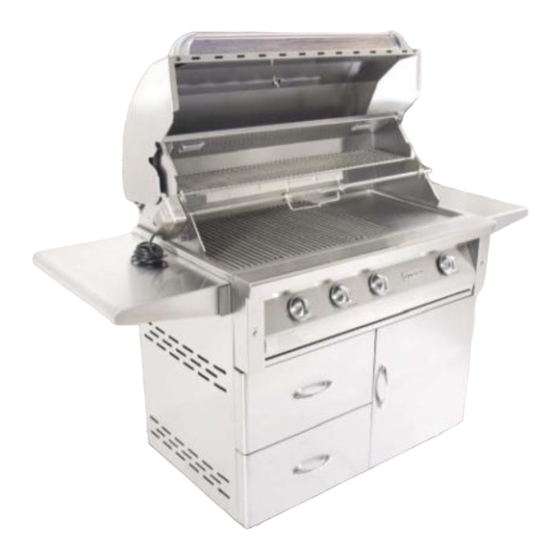
Page 26: Exploded Parts Views & Lists
EXPLODED VIEW AND PARTS LIST GF26 GRILL & CART ... - Page 27 GF26 PART LIST ITEM PART NO DESCRIPTION GF26 ITEM PART NO DESCRIPTION GF26 GF26P45 HOOD HANDLE SELF TAPPING SCREW ST4.2x9 GF26P46 HANDLE END CAP FLANGE SCREW M5x25 GF32P47A FIXING NUT—TEMP GAUGE PHILIPS HEAD SCREW M4X6 GF32P47 TEMP GAUGE FLANGE NUT M4 GF26P01 HOOD GF32CP01 SIDE SHELF GF32P44 HOOD BUMPER GF32CP11A SHELF BRACKET A GF26P02A REAR HOOD PANEL GF32CP11B SHELF BRACKET B GF02P02B LEFT SIDE‐REAR HOOD GF26CP04 UPPER BACK PANEL GF26P02C BRACKER‐WARMING RACK GF26CP03 26" CART BODY ASSEMBLY GF02P02D REAR INNER HOOD GF32CP05A DOOR HINGE A...
- Page 28 GF32 GRILL & CART...
- Page 29 GF32 PART LIST ITEM PART NO. DESCRIPTION GF32 ITEM PART NO. DESCRIPTION GF32 GF26P26A TEST POINT GF32P45 HOOD HANDLE GF32P25 MAIN VALVE GF26P46 HANDLE END CAP —TUBE BURNER 1.10mm GF32P47A FIXING NUT—TEMP GAUGE —SEAR BURNER 1.05mm GF32P47 TEMP GAUGE —TUBE BURNER 1.93mm GF32P01 HOOD —SEAR BURNER 1.78mm GF32P44 HOOD BUMPER GF32P24 BACK BURNER VALVE GF32P04A REAR HOOD PANEL GF32P27 FLEX TUBE‐BACK BURNER GF26P02B LEFT SIDE‐REAR HOOD GF32P28 KNOB GF26P02C BRACKET‐WARMING RACK GF32P29 LOGO PLATE...
- Page 30 GF32 PART LIST ITEM PART NO. DESCRIPTION GF32 GF32CP10 LP TANK SLIDE TRAY GF32CP10C BRACKET ‐ LP TANK SLIDE GF32CP10B RETENTION SCREW GF32CP07A 32' CART DOOR A GF32CP07A 32' CART DOOR B GF32CP08 DOOR HANDLE GF26CP09A CASTER GF26CP09B WHEEL 100 GF26CP06 MAGNETIC LATCH 102 GF32CP102 SIDE BURNER HOOD 103 GF32CP103 TOP GRATE ‐ SIDE BURNER 104 SB1P15 FIRE RING 105 SB1P14 FIRE RING PEDESTAL 106 GF32CP106 SIDE BURNER BODY ASSEMBLY 107 GF32P44 RUBBER BUMPER 108 GF32CP108 SIDE BURNER INJECTOR...
- Page 31 GF38 GRILL & CART...
- Page 32 GF38 PART LIST ITEM PART NO DESCRIPTION GF38 ITEM PART NO DESCRIPTION GF38 GF38P45 HOOD HANDLE GF38P26 MANIFOLD ASSEMBLY GF32P46 HANDLE END CAP GF26P26A TEST POINT GF32P47A FIXING NUT—TEMP GAUGE GF32P25 MAIN VALVE GF32P47 TEMP GAUGE —TUBE BURNER 1.10mm GF38P01 HOOD —SEAR BURNER 1.05mm GF32P44 HOOD BUMPER —TUBE BURNER 1.93mm GF38P04A REAR HOOD PANEL —SEAR BURNER 1.78mm GF26P02B LEFT SIDE‐REAR HOOD GF32P24 BACK BURNER VALVE GF26P02C BRACKET‐WARMING RACK GF32P27 FLEX TUBE—REAR BURNER GF38P04D REAR INNER HOOD...
- Page 33 GF38 PART LIST ITEM PART NO DESCRIPTION GF38 GF32CP10A SLIDE GF32CP10 LP TANK SLIDE TRAY GF32CP10C BRACKET ‐ LP TANK SLIDE GF32CP10B RETENTION SCREW GF38CP07A 38" CART DOOR A GF38CP07B 38" CART DOOR B GF26CP08 DOOR HANDLE GF26CP09A CASTER GF26CP09B WHEEL 100 GF26CP06 MAGNETIC LATCH 101 GF38CP14 UTILITY RACK 102 GF32CP102 SIDE BURNER HOOD 103 GF32CP103 TOP GRATE ‐ SIDE BURNER 104 SB1P15 FIRE RING 105 SB1P14 FIRE RING PEDESTAL 106 GF32CP106 SIDE BURNER BODY ASSEMBLY 107 GF32P44...
- Page 34 GFD30 GRILL & CART...
- Page 35 GFD30 PARTS LIST ITEM PART NO DESCRIPTION GFD30 ITEM PART NO DESCRIPTION GFD30 GFD30P49 HOOD HANDLE 48 GFD42P34A WIRE 1 GF32P46 HANDLE END CAP 49 GFD30P12B FRONT SHELTER GF32P47A FIXING NUT ‐ TEMP GAUGE 50 GFD42P34 IGNITIOR‐MAIN BURNER GF32P47 TEMP GAUGE 51 GFD30P35 IGNITOR BRACKET GFD30P01 HOOD 52 GFD42P27 SPACER GF32P44 HOOD BUMPER 53 GFD30P46A IGNITION WIRE ‐ BACK BURNER GFD30P05A REAR HOOD PANEL 54 GF32P29 LOGO PLATE GFD42P04...
- Page 36 GFD30 PARTS LIST ITEM PART NO DESCRIPTION GFD30 100 GF32CP10A SLIDE 101 GF32CP10 LP TANK SLIDE TRAY 102 GF32CP10C BRACKET ‐ LP TANK SLIDE 103 GF32CP10B RETENTION SCREW 104 GFD30CP07A 30" CART DOOR A 105 GFD30CP07B 30" CART DOOR B 106 GF26CP08 DOOR HANDLE 107 GF26CP09A CASTER 108 GF26CP09B WHEEL 109 GF26CP06 MAGNETIC LATCH 110 GFD30CP03 30" CABINET TOP 111 GF32CP102 SIDE BURNER HOOD 112 GF32CP103 TOP GRATE ‐ SIDE BURNER...
- Page 37 GFD42 GRILL & CART ...
- Page 38 GFD42 PARTS LIST ITEM PART NO DESCRIPTION GFD42 ITEM PART NO DESCRIPTION GFD42 GFD42P24 MAIN BURNER VALVE GFD42P49 HOOD HANDLE GF32P46 HANDLE END CAP TUBE BURNER—ORIFICE 1.30mm GF32P47A FIXING NUT ‐ TEMP GAUGE SEAR BURNER—ORIFICE 1.30mm GF32P47 TEMP GAUGE TUBE BURNER—ORIFICE 2.50mm GFD42P01 HOOD SEAR BURNER‐ORIFICE 2.2mm GF32P44 HOOD BUMPER GFD42P34A WIRE 1 GFD42P05A REAR HOOD PANEL GFD42P12B FRONT SHELTER ...
- Page 39 GFD42 PARTS LIST ITEM PART NO DESCRIPTION GFD42 GFD42CP04 42" UPPER BACK PANEL GFD42CP02 42" CART BODY GF26CP05A DOOR HINGE A GFD30CP12 TRANSFORMER BRACKET GFD30CP17 PROTECTIVE SLEEVE (180MM) GF26CP05B DOOR HINGE B 100 GF32CP10A SLIDE 101 GF32CP10 LP TANK SLIDE TRAY 102 GF32CP10C BRACKET ‐ LP TANK SLIDE 103 GF32CP10B RETENTION SCREW 104 GFD42CP07 42" CART DOOR ...
- Page 40 GF32 & GF38 WIRE DIAGRAM GFD30 WIRE DIAGRAM ...
- Page 41 GFD36 & GFD42 WIRE DIAGRAM NOTE: ...
- Page 42 ...
Need help?
Do you have a question about the DELUXE Series and is the answer not in the manual?
Questions and answers