Table of Contents
Advertisement
Quick Links
Part No. DOC 37 Rev. 12 September 2006
USER, INSTALLATION
and
SERVICING INSTRUCTIONS
GRANT VORTEX
Condensing Oil Boiler range
Kitchen, Kitchen System,
Utility and Utility System Models
with outputs up to 70 kW
For use with Kerosene only
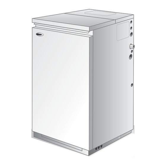
Utility model
Kitchen model
After installing the boiler leave these instructions with the User
This appliance is deemed a controlled service and specific regional statutory requirements
may be applicable
Advertisement
Table of Contents

Related Manuals for Grant Vortex 58/70


Summary of Contents for Grant Vortex 58/70
- Page 1 Part No. DOC 37 Rev. 12 September 2006 USER, INSTALLATION SERVICING INSTRUCTIONS GRANT VORTEX Condensing Oil Boiler range Kitchen, Kitchen System, Utility and Utility System Models with outputs up to 70 kW For use with Kerosene only Utility model Kitchen model...
-
Page 2: Table Of Contents
Net flue gas temp: ....Smoke No: ......SERVICE LOG It is recommended that the boiler should be regularly serviced, at least once a year, and the details entered in the Boiler Handbook by the service engineer. Grant Vortex Oil Boilers... -
Page 3: Introduction
To achieve the maximum efficiencies possible from combine to produce heat and water vapour. The water the Grant Vortex boiler, the heating system should be vapour produced is in the form of superheated steam in designed to the following parameters: the heat exchanger. -
Page 4: User Instructions
Set the HW and CH functions Utility and Utility System: Pull off the front access to TIMED. The boiler will now operate during the 'on' panel. periods set on the programmer. Fig. A Boiler controls (Kitchen model shown) Grant Vortex Oil Boilers... - Page 5 If this condition continually repeats, contact your About your fuel Service engineer. 4 Programmer (if fitted) - Refer to the instructions Grant Vortex boilers only operate on Class C2 Kerosene supplied with the Programmer. to BS 2869:1998. 5 Ventilation - Always ensure that the boiler has You should always quote this type of fuel when ordering adequate ventilation.
- Page 6 If the system requires frequent re-pressurising, ask your Installer or Service engineer to check the heating system for leaks and to check the expansion vessel air charge. Sealed system filling loop arrangement - Fig. B Grant Vortex Oil Boilers...
-
Page 7: Boiler Technical Information
Refer to Sections 4.1 and 4.7 for further details. IMPORTANT: On all models except 46/58 and 58/70 Return connections are stainless steel pipe (see above for size). Compression fitting MUST be used. Brass push-fit connectors are not suitable for use on stainless steel pipe. Grant Vortex Oil Boilers... - Page 8 The above settings may have to be adjusted on site for the correct operation of the burner. Gas Oil is not suitable for use with the Grant Vortex boiler range. When commissioning the air damper must be adjusted to obtain the correct CO level.
- Page 9 Flue centre line Flue spigot 22mm condensate drain 22mm stainless return LEFT SIDE VIEW FRONT VIEW RIGHT SIDE VIEW Fig 1a - Kitchen and Kitchen System 15/26 dimensions Fig. 1b - Utility and Utility System 15/26 dimensions Grant Vortex Oil Boilers...
- Page 10 Flue centre line opening for pipes. Flue spigot 22mm condensate drain 44 Dia. 44 Dia. LEFT SIDE VIEW FRONT VIEW RIGHT SIDE VIEW Fig. 1d - Utility 46/58 and 58/70 dimensions Grant Vortex Oil Boilers...
-
Page 11: General Boiler Information
Vertical concentric balanced flue kit For Conventional flue applications where a chimney is Extensions 225 mm, 450 mm, 950 mm and to be lined - Grant recommends the use of the Grant adjustable 275 to 450 mm ‘Orange’ flue system, specifically designed for the 45°... - Page 12 Regulations to comply with IMPORTANT Before starting any work on the boiler, or fuel supply Installation of a Grant Vortex boiler must be in please read the health and safety information given in accordance with the following recommendations:- Section 12 on page 47.
- Page 13 " to " BSP connection to the burner. If a two pipe system or male adaptor are available to purchase from Grant 'Tiger Loop' type de-aerator is used, an additional Engineering (UK) Limited), Part No. RBS104. See flexible fuel line (600 mm) and "...
- Page 14 " to " BSP 2 The de-aerator is connected close to the boiler as a male adaptor are available to purchase from Grant two pipe system (omitting the non-return valve) as shown in Fig. 5. Refer to the manufacturers Engineering (UK) Limited), Part No. RBS104. See instructions supplied with the de-aerator.
- Page 15 7 Flexible fuel lines and adaptors are available to 6 Any room thermostat or frost thermostat used must purchase from Grant Engineering (UK) Ltd. be suitable for use on mains voltage. 7 In the event of an electrical fault after installation...
- Page 16 For proper combustion of fuel and effective near the boiler. discharge of combustion products to the open air. Grant Vortex Oil Boilers...
- Page 17 Suitable conventional flue systems (Orange system) are available from Grant UK - see Fig. 10. 1 The flue must terminate in a down draught free area, Boiler i.e.
- Page 18 Grant Vortex oil fired including the 58/70 - is 100 mm (4 in). condensing boilers. Grant recommends the use of the Grant 'Green' flue Contents of Grant EZ-Fit Flexi Pack system components for this application. Refer to The pack includes a terminal/top plate/flexi flue adaptor, Section 4.1 for details.
- Page 19 Apart from a conventional flue, several balanced flue Extensions are available which extend the flue by options are available for use with the Grant Vortex 225 mm, 450 mm or 950 mm. An adjustable boilers. All are suitable for use with Class C2 kerosene.
- Page 20 GK90 (15 - 26 kW) intake GK200 (26 - 46 kW) DO NOT GK90S - short (15 - 26 kW) OBSTRUCT GK200S - short (26 - 46 kW) Components and Part Numbers Fig. 10a - External balanced flue (Green system) Grant Vortex Oil Boilers...
- Page 21 Distances measured to rim of terminal. * 600 A Below a gutter or sanitary pipework Horizontal from an opening, air brick or window Clearances recommended by Grant Above ground or balcony level Engineering (UK) Limited in accordance with *600 D Below eaves or balcony British Standards and Building Regulations.
- Page 22 - to leave the pipe ends with a slight radius and free from any burrs or sharp edges. Pipes to be used with these fittings should not be cut square using a hacksaw. Grant Vortex Oil Boilers...
- Page 23 - before the boiler is connected 1 All Grant Vortex boilers are suitable for use with and then again after the system has been heated and is sealed systems complying with the requirements of still hot.
- Page 24 If thermostatic radiator valves are fitted, the system must incorporate an adequate by-pass. Fig. 14 - Sealed system boilers Grant Vortex Oil Boilers...
- Page 25 40° C to prevent internal corrosion of the boiler water jacket. 26/36 System boiler shown. For non system boilers pockets are on side of pipe. Fig. 15a Thermostat phial position - 26/36 only Grant Vortex Oil Boilers...
- Page 26 4 - GENERAL BOILER INFORMATION Pipework materials 4.16 General - Grant boilers are compatible with both For boilers installed where it is not possible for the pipe copper and plastic pipe. Where plastic pipe is used it to fall towards the point of discharge - either internally must be of the oxygen barrier type and be of the into a waste system or externally to a gulley - e.g.
- Page 27 Backfill the hole around the soakaway tube with 10 mm overflow outlet is readily visible and that any limestone chippings. condensate overflowing from the outlet cannot cause either a hazard to persons or damage to surrounding property or equipment. Grant Vortex Oil Boilers...
-
Page 28: Boiler Installation
Fig. 19 - Low level balanced flue Fig. 19a - Low level balanced flue (Yellow System) and Starter kit (Green System) Model Dimension (mm) B dia Utility 46/58, 58/70 1102 Utility 26/36, 36/46 and Utility System 26/36, 36/46 All other models Grant Vortex Oil Boilers... - Page 29 B dia 1595* 2015 - 2335 Utility 46/58, 58/70 1280* 1700 - 2020 Utility 26/36, 36/46 and Utility System 26/36, 36/46 1215* 1715 - 2115 All other models *Dimension A for Starter section and elbow/terminal only Grant Vortex Oil Boilers...
- Page 30 6. If the Grant ‘Green’ system (100 mm rigid twin- condensate pipework to be run through the back of the wall flue) is to be fitted to the boiler then the Grant boiler. It will be necessary to remove the back panel from the CF adaptor kit (Ref.
- Page 31 It is recommend that the boiler should be connected to a switched mains power supply from a programmer or control system. If a Grant plug-in programmer is used, a permanent 240 V mains supply (fused at 5 Amp) must be taken to the boiler. A three core cable is required to connect the boiler terminal block to the live supply.
- Page 32 5 Air damper adjustment screw 2 Control box 6 Air supply tube connection (balanced flue) 3 Reset button with lock-out lamp 7 Pump pressure adjustment screw 4 Flange with gasket (do not remove from boiler) 8 Pressure gauge connection Grant Vortex Oil Boilers...
- Page 33 Leave the top copy with the User. Retain the carbon turn. Replace the plug and cap. copy. Ensure that the User Information pack (supplied with the boiler) is handed over to the Householder. Grant Vortex Oil Boilers...
-
Page 34: Commissioning
4 Connect a combined vent manifold and pressure the burner off. gauge to the pressure gauge connection port on the oil pump. See Fig. 7. Open the vent screw on your vent manifold to vent the supply while the pump is running. Grant Vortex Oil Boilers... - Page 35 (and pressurise if a sealed system) the system. 20 A suitable central heating system inhibitor must be added to protect the system against the effect of corrosion. 21 Close the front door panel (Kitchen models) or replace the front panel (Utility models). Grant Vortex Oil Boilers...
-
Page 36: Information For The User
Allow the boiler to cool. or damaged. The data label on the inside of the case side panel will 2 Run the boiler and check the operation of its indicate the fuel used and the nozzle fitted. controls. Grant Vortex Oil Boilers... - Page 37 9 Remove the condensate trap and check that it is not blocked and is operating correctly, i.e. the float is free to move. Clean the trap and float as required. Fig. 25 - 26/36 and 36/46 baffles Grant Vortex Oil Boilers...
- Page 38 'A' in Fig. 29, tighten the screw. To adjust the electrodes: Loosen the electrode IMPORTANT: The electrode settings given above clamp screw and move the electrode unit to achieve MUST be observed the gap 'B' in Fig. 29, tighten the screw. Grant Vortex Oil Boilers...
- Page 39 To ensure safe and efficient operation of the boiler it is important that re-commissioning is carried out, especially combustion checks (CO level, flue gas temperature and smoke number) after the boiler has been serviced. Refer to the Commissioning instructions starting on page 34. Grant Vortex Oil Boilers...
-
Page 40: Wiring Diagrams
Grant Electronic 7-day Plug-in Programmer Colour code: Br - Brown, R - Red, Bl - Blue, Y - Yellow, G/Y - Green/Yellow, Blk - Black Fig. 31 Control panel wiring diagram - Kitchen System models Fig. 32 Grant Vortex Oil Boilers... - Page 41 9 - WIRING DIAGRAMS Utility boiler control panel wiring diagram Fig. 33 - Utility boiler Utility System boiler control panel wiring diagram Fig. 34 - Utility System boiler Grant Vortex Oil Boilers...
- Page 42 Utility models with Honeywell Y Plan (HW controlled by mid position valve) Fig. 35 Typical control system wiring diagram (Kitchen models) Kitchen models with Honeywell S Plan (HW & CH controlled by two valves) Fig. 36 Grant Vortex Oil Boilers...
-
Page 43: Fault Finding
10 - FAULT FINDING 10.1 Burner fault finding Grant Vortex Oil Boilers... -
Page 44: Fault Finding
12 Combustion fumes smell. Check boiler cleaning cover and seal are correctly fitted. Check burner is correctly fitted onto flange. Check flue is correctly sealed into flue outlet of boiler. Check the condensate pipe and trap are operating correctly. Grant Vortex Oil Boilers... -
Page 45: Burner Spares
3008649 RBS118 Fan - 36/46 3005788 RBS151 Control box assembly 3008652 RBS103 Photocell 3008646 RBS115 Solenoid lead 3008851 RBS139 Capacitor 4.5 µF 3002837 RBS149 Cover 3008879 RBS141 Seal kit 3008878 RBS140 Air tube spigot 3062774 RBS143 Grant Vortex Oil Boilers... - Page 46 Filter - 'O' ring 3008653 RBS122 Photocell 3008646 RBS115 Regulator 3008651 RBS120 Cover 3008962 RBS168 Needle valve 3007582 RBS109 Electrode 3020121 RBS158 Control box assembly 3008652 RBS103 Capacitor 5 µF 3008960 RBS167 Cover 3008649 RBS118 Connector 3003602 RBS35 Grant Vortex Oil Boilers...
-
Page 47: Health And Safety Information
Take care to prevent clothing, especially underwear, from becoming contaminated with oil. Do not put oily rags or tools in pockets, especially trouser pockets. Have first-aid treatment at once for an injury, however slight. Do not inhale any vapours from mineral oils. Grant Vortex Oil Boilers... -
Page 48: Ec Declaration Of Conformity
All goods sold are subject to our official Conditions of Sale, a copy of which may be obtained on application. © Grant Engineering (UK) Limited 2006. No part of this manual may be reproduced by any means without prior written consent.
Need help?
Do you have a question about the Vortex 58/70 and is the answer not in the manual?
Questions and answers