Table of Contents
Advertisement
Advertisement
Table of Contents

Related Manuals for UTAH SCIENTIFIC UTAH-100/UDS 20x20


Summary of Contents for UTAH SCIENTIFIC UTAH-100/UDS 20x20
- Page 1 UTAH-100/UDS Compact Router Series System Setup and Operation...
-
Page 2: Copyrights And Trademarks
Printed in U.S.A. • Copyrights and Trademarks © 2015 Utah Scientific, Inc., All rights reserved. Any use or reproduction of this guide’s contents without the prior written consent of Utah Scientific, Inc. is strictly prohibited. UTAH 100 is a trademarks of Utah Scientific, Inc. - Page 3 Operation of this equipment in a residential area is likely to cause harmful interference, in which case, the user will be required to correct the interference at their own expense. Shielded cables must be used to ensure compliance with the FCC Class A limits.
-
Page 4: Declaration Of Conformity
Following the provisions of the Directive(s) of the Council of the European Union: EMC Directive 89/336/EED • Low Voltage Electrical Directive 72/23/EEC • Utah Scientific, Inc. hereby declares that the product specified above conforms to the above Directive(s) and Standard(s). - Page 5 Important Safeguards and Notices This section provides important safety guidelines for the Operator and Service Personnel. Specific warnings and cautions are found throughout the guide where they apply, but may not appear here. Please read and follow the important safety information, specifically those instructions related to risk of fire, electric shock, or injury to persons.
- Page 6 Dangerous voltages exist at several points in this prod- • uct. To avoid personal injury, do not touch exposed con- ductors and components while power is on. Do not insert anything into either of the systems two-power supply cavities with power connected. Do not wear hand jewelry or watches when troubleshoot- •...
- Page 7 Company Information Utah Scientific, Incorporated 4750 Wiley Post Way, Suite 150 Salt Lake City, Utah 84116-2878 U.S.A. Telephone: +1 (801) 575-8801 • FAX: +1 (801) 537-3098 • Technical Services (voice): +1 (800) 447-7204 • Technical Services (FAX): +1 (801) 537-3069 •...
- Page 8 Warranty Policies Hardware Warranty Utah Scientific, Inc. warrants to the original purchaser that the Utah Scientific hardware is free from defects in materials and workmanship and will perform substantially in accordance with the accompanying written materials under normal use and service for a period of two (2), five (5), or ten (10) years from the date of shipment.
- Page 9 These rights may vary in certain states/jurisdictions. No liability for consequential damages. To the maximum extent permitted by applicable law, in no event shall Utah Scientific or its suppliers be liable for any damages whatsoever (including without limitation, damages for loss...
-
Page 11: Table Of Contents
Table of Contents Table of Contents Section 1 Overview Introduction ....................1-1 System Architecture ................. 1-3 System Diagrams ..................1-4 UDS 10x10 ................1-4 UDS 20x20 ................1-4 8x32 DA ..................1-5 UDS XY ..................1-5 Installation ..................... 1-6 Power Connections .................. 1-6 Ethernet Connections ................ - Page 12 System Interface ..................1-18 Input Switches and LED’s ................ 1-19 Output Switches and LED’s ..............1-19 Button Legends ..................1-19 Section 2 Network Configuration Introduction ....................2-1 System Setup Requirements ................. 2-2 UTAH-100/UDS Network Configuration ............2-3 New Configuration on Independent Network ...........
- Page 13 Table of Contents Multiple Destination Selection ..........3-31 Audio ..................3-32 Macro buttons ................3-32 Salvos ....................... 3-34 Preset List Window ................... 3-35 Section 4 The Control Applet Introduction ....................4-1 The UTAH-100/UDS CP ................4-2 Front View ....................4-2 Rear View ....................4-2 Setup ......................
- Page 14 Multi-Rate Digital Output Card ..............5-3 FLEX-I/O Option ..................5-3 Alarm Conditions .................... 5-4 Appendix A RCP1 Protocol for UDS Matrix Refresh Report Enable ............... A-1 Matrix Refresh Report Disable ..............A-1 Matrix Change Report Enable ............... A-2 Matrix Change Report Disable ..........
- Page 15 Table of Contents Appendix D Maintenance Functions In This Appendix .................... D-1 Changing Button Legends ................D-2 Using the Template .................. D-3 Removing and Inserting button legends ........... D-5 Ordering Parts ..................D-6 Table of Contents...
- Page 16 UTAH-100/UDS Setup & Operations Guide...
-
Page 17: Introduction
Introduction Section 1 Overview Introduction The UDS Utility Router Series is a compact, self-contained routing switcher system designed for SDI video routing. Using common components, systems of 10x10, 20x20 and 8x32 DA can be constructed in a 1 RU chassis using standard BNC connectors. All necessary control and cooling components reside in the chassis. - Page 18 Overview The video path within the router is capable of 18 Mb/Sec to 3Gb/sec. Reclocking is performed at 270Mb/Sec, 1.485Gb/Sec and 2.970 Gb/Sec, and any other frequency is passed with the reclocking automatically bypassing. The reclocking feature is DVB-ASI compatible. Very long cable lengths are achieved by reclocking each input signal directly after it is received, providing the cleanest signal possible to the system.
-
Page 19: System Architecture
Introduction System Architecture Each of the three possible configurations begin with a Base Crosspoint card, the 121352-1. This card contains all control circuitry, crosspoints, 8 dedicated inputs, 10 dedicated outputs, and two Bi-Directional ports. This card also has two expansion slot connections for additional boards. -
Page 20: System Diagrams
Overview System Diagrams UDS 10x10 UDS 20x20 System Setup... -
Page 21: 8X32 Da
Introduction 8x32 DA UDS XY Section 1... -
Page 22: Installation
140033-08 power supply here There are two captive-nut power connections on the rear of the chassis. They accept input from the 140033-08 Utah Scientific 30W power supply. Either port can be used, and one or two supplies can be connected or redundancy. -
Page 23: Ethernet Connections
Installation Ethernet Connections Figure 1-5. LH rear panel connections - Ethernet Jack Using standard CAT-5 or CAT-6 Ethernet cable, connect this port to an Ethernet Switch. This port is an Auto MDI-X port, so if desired it can be connected directly to a PC or UDS Remote Control Panel without the need for a crossover cable. -
Page 24: Rcp-1 Serial Port
The DB9 Serial port can be used to remotely control the router using standard RCP-1 protocols. Contact Utah Scientific Customer Support for a copy of this protocol. The baud rate, data/start/stop bit configuration and 232/422 mode of this port are configured in the Web Based GUI described in Section 2 of this manual. -
Page 25: Diagnostic Serial Port
Figure 1-8. LH rear panel connections - RJ45 Serial Port The RJ-45 serial port is used for Diagnostic connections only. Utah Scientific Service Personnel may ask you to connect a serial port here to diagnose certain issues. The system is delivered with an adapter, USI PN 140033-15, that allows you to connect a CAT5 patch cord to this port, then to the adapter, and then to an RS-232 port on a standard PC. -
Page 26: 140033-15 Adapter Pinout And Schematic
Overview 140033-15 Adapter Pinout and Schematic Figure 1-10. Pinout Schematic DB9S to RJ45 Name Wire Color Brown White Blue Reference Connections Figure 1-11. Rear Panel - Center BNC on the lower row The BNC on the lower row of the router directly in the center is for an analog reference signal used to switch the router in vertical interval. -
Page 27: Video Connections
Installation Video Connections Figure 1-12. Rear Panel - label indicating IO Numbers The 40 BNC connectors have different numbering based on the 3 different configurations. Each configuration has a label indicating which BNC’s are which. Refer to this label when connecting Input or Output Coax cables to the BNC’s. -
Page 28: Front Panel Controls And Indicators
Overview Front Panel Controls and Indicators Power LED LINK RESET Reset Switch Figure 1-13. Power LED – Green indicates normal operation. – Red indicates a fault with temperature or power supplies. Reset Switch – Pressing this switch momentarily will reset all processing functions. -
Page 29: Components
Components Components Base Crosspoint Card (121352-1) Revision 02 Figure 1-14. Crosspoint Card - #121352-1 Power Supplies This system utilizes the standard external 12 Volt DC power supply, 140033-08. It accepts one or two supplies for redundancy. Diode D2 acts as an O ring diode for the two external power supplies. -
Page 30: Control Circuitry
Overview Control Circuitry The control circuitry for this card is centered around a Freescale K60 MCU and Xilinx FPGA. The CPU interfaces control inputs from Ethernet and Serial to the FPGA, which controls all of the switching functions within the router. FPGA and Memory. -
Page 31: Crosspoint
Components Crosspoint The crosspoint is a M23636 (U28). All input signals are AC coupled into the device and outputs are DC Coupled. A heatsink is installed on the IC. Input Circuits Inputs 1-8 are made up of M21564 cable equalizers that feed M21350 reclocking components. -
Page 32: Expansion Input Card (121353-1) Revision 02
Overview Expansion Input Card (121353-1) Revision 02 Figure 1-15. 121353-1 Here This card is a simple board that receives and reclocks 10 input signals and then drives them to the base crosspoint card. It has local power supplies and control circuitry. Power Supplies The 12 VDC from the base card is fused and then regulated to 3.3, 2.5 and 1.2 VDC 2 amp rails by U17, U15 and U14 respectively. -
Page 33: Expansion Output Card (121354-1) Revision 02
Components Expansion Output Card (121354-1) Revision 02 Figure 1-16. 121354-1 Here This card is a simple board that receives 10 output signals from the crosspoint core and drives them out of BNC’s. It has a local power supply and control circuitry. Power Supplies The 12 VDC from the base card is fused and then regulated to 3.3 VDC by U11. -
Page 34: Local Control Panel (121355-1) Revision 02
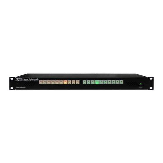
Overview Local Control Panel (121355-1) Revision 02 Figure 1-17. Front Panel - #121355-1 This assembly is a simple control panel that has 10 or 20 buttons to select outputs and 10 or 20 buttons to select inputs. The output buttons are backlit in amber (Red+Green) and the inputs are backlit in green. -
Page 35: Input Switches And Led's
Components Input Switches and LED’s Each LED is backlit by virtue of a voltage divider (See R58 and R59 for led DS20) and actively lit, when appropriate, by an associated transistor turning on (See Q10). Each transistor is driven from a separate output of the TCA6416 I2C IO expander associated with that bank of LED’s (10 per). - Page 36 Overview 1-20 System Setup...
-
Page 37: Network Configuration
Introduction Section 2 UTAH-100/UDS Browser Utility Network Configuration Introduction This guide describes the network configuration for the UTAH-100/UDS Router and Panel. Using two setup scenarios; New Configuration on an Independent Network, and New Configuration on an Existing Network. These are the first steps required to configure and control the system. -
Page 38: System Setup Requirements
Network Configuration System Setup Requirements • Windows™ operating system 7 • Java 7.07™ or newer • Internet Explorer™, Firefox™, or Chrome™ • Ethernet connection All UDS devices - PC, Router, and Panel - connect over Ethernet on a house network, or within a stand-alone (direct) mode. -
Page 39: Utah-100/Uds Network Configuration
UTAH-100/UDS Network Configuration UTAH-100/UDS Network Configuration New Configuration on Independent Network This scenario consists of a router and a panel working in a stand-alone mode with one or more PC to complete an independent, stand alone network. FIGURE 1. New configuration on an independent network is relatively simple, involving Ethernet connection between the PC and devices (router and panel) only, as a stand alone network. - Page 40 Network Configuration To change the devices to use non default addresses, see New Configuration on an Exist- ing Network (next). Also note, the PC and devices (router and panel) must occupy the same subnet. See your network administrator for configuration assistance if no default subnet appears.
- Page 41 UTAH-100/UDS Network Configuration New Configuration on an Existing Network This procedure describes new configuration on an existing network. Use this routine if you need to modify the router or panel’s network parameters. The steps below are based on the default set of parameters. On the PC, click Control Panel, Network and Internet, Network Sharing Center, then Change Adapter Settings.
- Page 42 Network Configuration When the following window appears, right-click the icon to produce the drop-down menu, then select Properties. FIGURE 3. The following window will appear. FIGURE 4. Network Configuration...
- Page 43 UTAH-100/UDS Network Configuration Select Internet Protocol Version 4, then click the Properties button. The following win- dow will appear. FIGURE 5. Click the second radio button down to set a static IP address. FIGURE 6. Section 2...
- Page 44 Network Configuration Enter the following address into the indicated cell (192.168.5.2) FIGURE 7. Accept the Subnet mask default, then click OK. Now connect your PC or laptop to the router with a standard Ethernet cable. Note: A crossover cable (typically used with an Ethernet connection) is not necessary as the signal ‘switch’...
-
Page 45: Router Applet Activation And Configuration
Router Applet Activation and Configuration Router Applet Activation and Configuration Launch your preferred browser and complete the following steps: a. Log into the Router Applet by entering 192.168.5.180 into your browser’s URL line (default). If your router is using a different address than the default, enter it into the browser. - Page 46 Network Configuration c. When the Router icons appears, select “Router Configuration”. FIGURE 9. Note: You will only be able to connect if the browser window (shown in Figure 9) indicates “Applet ready for login.” d. Enter Username “admin” (default) - in the username entry box e.
- Page 47 Router Applet Activation and Configuration Click the Data Comm (radio button) to change the network configuration. FIGURE 10. Note: The program will display the router’s IP address (IP Address cell, above). It is important however that Net mask and Gateway remain constant among all devices, and to keep the DHCP box unchecked.
-
Page 48: Panel Applet Activation And Configuration
Network Configuration Panel Applet Activation and Configuration Make sure the panel is plugged into the same network as the PC, and that the PC is set to the same subnet as the panel. This procedure allows the configuration from the Panel Applet in the absence of a physical router connection. - Page 49 IP addresses. The default username and password is admin, in both cases. Once you have logged in, click the configuration icons to activate the configuration dialogs. For additional assistance, please contact Utah Scientific Customer Service - 1(800) 447-7204. Section 2...
- Page 50 Network Configuration 2-14 Network Configuration...
-
Page 51: The Router Applet
Router Configuration Section 3 UTAH-100/UDS Browser Utility The Router Applet Router Configuration Router Configuration is activated by launching the browser applet (using the supplied default IP address). This section contains the steps involved in activation and operation of the UTAH-100/UDS Router Applet. Section 3... - Page 52 The Router Applet The Router applet must be connected to the actual router to communicate properly. Once the necessary hardware is in place, start the application with the provided IP address, then launch the applet by clicking the Router Configuration icon. Figure 3-1.
-
Page 53: Security
Router Configuration This will activate the setup window. During a successful login, all associated accounts are loaded into the system at the time of the initial launch (Current User). Figure 3-3. Security The default user is listed in the 'Current User' cell. You can change users from the list of previously designated users (Switch User button). -
Page 54: Data Comm
The Router Applet Data Comm TCP RCP-3 (Network) This dialog is used to set Device Communications parameters. Network IP address, netmask, and gateway parameters are edited at this location along with the RCP-3 port setting. Alternatively, you can select DHCP to automatically set network parameters. The only way to verify the IP address setting in DHCP mode is to access the DHCP server. -
Page 55: Dhcp
Router Configuration DHCP In certain circumstances the default IP address is unusable and DHCP connectivity is expected. Click the DHCP box to activate the connection. The address cells will gray out when the box is clicked. The only way to verify the IP address setting in this mode is to monitor the DHCP server via serial connection. -
Page 56: Sources
The Router Applet Sources The program defaults with all sources configured. Since this is not the likely desired configuration, highlight the unwanted sources and click the Remove button. Figure 3-9. Source Creation New Sources are defined and added by clicking the Replicate button. Figure 3-10. - Page 57 Router Configuration In this example, the prefix is the three character descriptor for camera. Numeric suffix start is the 3 digit end definer associated with the device. Increment, and starting port number are all assigned as number ‘1’. The Description is a long form identifier, with ‘suffix’ placed inside ‘less than’...
- Page 58 The Router Applet Source creation from within the list Highlight the line and enter the definitions for Port, Name, and Description. Figure 3-13. Using this option to add Sources will not allow you to manually enter the View method. Click the View radio button to make this modification.
- Page 59 Router Configuration Your new view will be associated when you return to the Sources window. Figure 3-16. Section 3...
- Page 60 The Router Applet Destinations The program defaults with all destinations configured. Since this is not the likely desired configuration, highlight the unwanted sources and click the Remove button. Figure 3-17. Destination creation New Destinations are defined and added by clicking the Replicate button, or by entering data in the table directly.
- Page 61 Router Configuration In this example, the prefix is the three character descriptor for camera. Numeric suffix start is the 3 digit end definer associated with the device. Increment, and starting port number are all assigned as number ‘1’. The Description is a long form identifier, with ‘suffix’ placed inside ‘less than’...
-
Page 62: Destination Creation From Within The List
The Router Applet Destination Creation from Within the List Highlight the line and enter the definitions for Port, Name, and Description. Figure 3-21. Do this to overwrite the lines contents when the cursor becomes active. Using this option to add Destinations will not allow you to manually enter the View method. Click the View radio button to make additional modifications. - Page 63 Router Configuration Click the checkbox associated with the new Destination, then highlight the desired view type within the View list. Figure 3-23. You can also click the Destinations radio button and ‘Replicate’ in the same manner as with Sources. This involves adding Destinations to the list in the correct sequence. The Replicate dialog window contains a pop down menu at the bottom, which will contain any previously created Destination blocks.
-
Page 64: Panel Views
The Router Applet Panel Views Organizing The Views selection is a way to organize Sources and Destinations into manageable groups for the router control window. Views will appear within the Source and Destination lists immediately after editing. To facilitate this, click the Panel Views radio button, select the desired View from the list on the left, then click the checkboxes within the next two devices you would like associated with the View. -
Page 65: Sorting Option
Router Configuration Sorting Option With Panel Views selected, the Sorting Option is a way to organize Sources and Destinations into display lists (Router Control applet) based on a router or alphabetic port designation. To access the sorting option, click the Panel Views radio button, the parameters you would like to sort within, then indicate the All Sort Order (Alpha or Router) and click the Program button. - Page 66 The Router Applet Router Sort This is an example of the display that will appear within the Router Control Applet when Router Sort is indicated (Config Applet). Sorting is completed by router port. Figure 3-25. Router Sort 3-16 The Router Applet...
- Page 67 Router Configuration Alpha Sort And this is an example of the display that will appear within the Router Control Applet when Alpha Sort is indicated (Config Applet). Sorting is completed by alpha numeric port. Figure 3-26. Alpha Sort Section 3 3-17...
-
Page 68: Destination Blocks
The Router Applet Destination Blocks The Destination Block is essentially a way to assign a destination grouping as a DA. Any pre-configured destination blocks will display in the drop down list inside this dialog window. This saves time by assigning an entire group, or block at once. Click the Dst Block checkbox to activate this feature. -
Page 69: Salvos
Router Configuration Salvos The Salvo is a mechanism for storing multiple takes to be conveniently triggered at a later time. Salvos will appear as new sources in the system and will trigger the configured takes when selected. Figure 3-28. Section 3 3-19... - Page 70 The Router Applet Select the desired Source and Destination from the lists, then click the “Add” button to place the new Salvo to the listing on the right. Figure 3-29. 3-20 The Router Applet...
- Page 71 Router Configuration You can now verify your new Salvo by accessing the View dialog area (View radio button). Note that a new Source is listed within the corresponding column. Figure 3-30. Your new Salvo will also be displayed inside the Router Control applet. Section 3 3-21...
-
Page 72: Accounts
The Router Applet Accounts The ‘UDS System’ defaults with 3 pre-defined use accounts. You can edit the passwords, modify, delete, or add accounts as needed for your operation. Figure 3-31. • Roles allow permissions for various system attributes; the actual creation, modification, or deletion of accounts (admin). - Page 73 Router Configuration • Preset controls the ability to turn preset on or off; Preset ON allows constant preset activation if needed. Views to be associated with given accounts are defined by the checkboxes in the admin View List. While all layouts are available to any user for status view, destination selection and the ability to make takes are defined within this listing.
-
Page 74: Save Button
The Router Applet Save Button The router configuration is saved to a file on your computer. If you want to save the current state of the router connections, make sure the corresponding check box is indicated within the Router Configuration dialog window (right side). Note: When you program the router (Program Router button), a warning dialog will appear indi- cating that the current configuration ‘Contains Router Status - Do you wish to Switch the Router?’... -
Page 75: Router Control
Router Control Router Control Source and Destination Management Destination buttons are contained on the left side of the display, with the Source status indicated above each button. The Control panel layout (illustrated below) will follow your own panel configuration. Destinations are selected on the left side of the display by clicking the labeled button, then the intended Source is selected (clicked) on the right side of the display. - Page 76 The Router Applet When you select a Destination and make a Take, the Destinations will automatically reset if the checkbox below is set. Figure 3-34. Otherwise the Destinations will remain selected allowing you to make multiple takes on the same Destinations without having to re-select each one. 3-26 The Router Applet...
- Page 77 Router Control Destinations can be locked or protected by clicking the corresponding buttons within the lower-left of the display. Figure 3-35. Takes can still be made on Destinations in Protect mode locally, while remote users will not have access to protected Destinations. Locked Destinations are not switchable by anyone until the lock is actually cleared.
-
Page 78: Preset (Checkbox)
The Router Applet Preset (checkbox) If the Preset box is checked (Controls group area), the ‘Take’ button (lower right) will blink, waiting for the user to activate the take by a button click. Figure 3-36. The ‘status’ will alternate between what currently exists, and what the action will be once the Take commences. - Page 79 Router Control All UDS Control activity is logged in the Status box in the lower right portion of the display. Figure 3-37. Section 3 3-29...
-
Page 80: Changing The Button Color Scheme
The Router Applet Changing the Button Color Scheme Changing the Source button color schemes is useful for designating status colors for different equipment sets. Right-click on a Source button to produce a color picker window. Use the Auto button to [ask the system to] uniquely color all Source buttons. This is useful when original button colors are needed quickly. -
Page 81: Destination Reset Mode (Checkbox)
Router Control Destination Reset Mode (checkbox) The Destination Reset Mode checkbox (Dst reset mode) will control the activity, or what happens immediately following the take. Specifically, when checked, the Destination button itself is no longer selected (or highlighted) after the Take is made. If not checked, the Destination button will remain selected after the Take is made. -
Page 82: Audio
The Router Applet Audio Take status is indicated by the audio control at the bottom of the display. If the Mute box is unchecked, takes are heard and controlled with the corresponding audio slider bar. Figure 3-40. Macro buttons A series of Takes can be saved as a Macro while in the Preset mode. Macros work like Salvos, but are saved to the PC where they are configured and cannot be used system wide. - Page 83 Router Control Macros are saved in the listing, or renamed by clicking the selection at the bottom of the pop up window. Figure 3-42. Section 3 3-33...
-
Page 84: Salvos
The Router Applet Salvos The Salvo buttons inside the Sources group area allow you to activate Takes on multiple Destinations. As an example, one Salvo button may control multiple Destinations with pre-configured Sources for each salvo destination. Figure 3-43. Salvos are set up on a system-wide basis with the configuration window. 3-34 The Router Applet... -
Page 85: Preset List Window
Router Control Preset List Window The waiting takes will be listed within the display once a Destination and Source have been selected. Figure 3-44. Please continue on to the next section, Hardware Based Control Panel Configuration and Operation, for UDS panel setup and maintenance detail. Section 3 3-35... - Page 86 The Router Applet 3-36 The Router Applet...
-
Page 87: The Control Applet
Introduction Section 4 The Control Applet Introduction As discussed in Section 3, the UTAH-100/UDS can be controlled and monitored using a virtual control via a built-in web interface, or external hardware control panel via Ethernet. This section describes the setup, configuration and operation of the optional external control panel. -
Page 88: The Utah-100/Uds Cp
The Control Applet The UTAH-100/UDS CP The external hardware control panel and virtual control via Ethernet extends the functionality of the system to local and remote users as necessary. Front View Figure 4-1. Rear View Figure 4-2. Setup Use the following steps to install the Utah-100/UDS Systems into the rack frames: 1. -
Page 89: Panel Configuration
Panel Configuration Panel Configuration Panel Configuration is activated by launching a web browser and entering the panel’s IP address as the URL. The panel must be connected to the network in order to communicate properly. Click the Config icon to activate the UDS Panel Config applet. Figure 4-3. - Page 90 The Control Applet Use the radio buttons in the Panel Configuration section to navigate through the configuration screens; System, Network and Encoding. Figure 4-5. Save - Saves the current panel configuration to a file on your computer. Open accesses the directory containing previously saved panel configuration files. Print allows you to produce a listing of all buttons and assignments when encoding is complete.
-
Page 91: System
Panel Configuration System When selected, the System radio button displays the current panel configuration detail (System Info area). Figure 4-6. You can edit the System Name, view the system version number, and update system components from the System Info screen. Network Network configuration is essentially the same as network setup during Router configuration, with the exception that the user must specify the router IP address. -
Page 92: Network Parameters
The Control Applet Network Parameters Panel ID and address configuration is entered at the top of the display. 5001 is the Port default. Figure 4-8. When indicated, the DHCP checkbox will allow the program to complete its own designation. Encoding Once you have logged in and the window is open, the activated panel layout will mimic the setup actions of the external control panel itself. -
Page 93: Panel Layout - Config Controls
Panel Configuration Panel Layout - Config Controls The current panel’s IP address is displayed, along with the controller to which the panel is connected. Current Controller Current Panel Figure 4-10. This sets the destination applied to a single panel. Figure 4-11. Section 4... - Page 94 The Control Applet Buttons are assigned by highlight device selections (1 or more), then dragging the list items to the individual buttons. Figure 4-12. A Multi Dst Layout with more than one destination assigned to the panel’s destination buttons. External Control Panel...
-
Page 95: Layouts - Single And Multi-Dest
Panel Configuration Layouts - Single and Multi-Dest Single Destination When indicated, 32 Sources are defined with one Destination selected for control. In this configuration you can drag Sources one at a time or double-click Sources from the list area (Dst and Src Devices list area). Figure 4-13. -
Page 96: Multi-Dest Layout
The Control Applet Multi-Dest layout Multi-Dest mode allows the user to simultaneously control 16 Destinations and 16 Sources. As with Single Destination mode, the page navigation includes three pages for operation. Figure 4-14. In this mode you may drag destinations or sources to the panel buttons, with Destinations on the yellow buttons and Sources on the green buttons. -
Page 97: Xy-32 Configuration
Panel Configuration XY-32 Configuration Click the corresponding radio button to activate the XY-32 Layout. Figure 4-15. This layout contains two pages; one page for 32 Destinations and one for 32 Sources. Section 4 4-11... - Page 98 The Control Applet Dragging Destinations from the listing (lower right) will apply to one button block only. In this way, list selections will never overflow into the next button block. Figure 4-16. Click the Page Up and Page Down buttons to view the configured panel pages. Figure 4-17.
- Page 99 Panel Configuration Click the Configure Panel button when button population for both Destination and Source buttons are complete. Figure 4-18. Section 4 4-13...
-
Page 100: Print Option
The Control Applet Print Option The Panel Configuration contains a Print option that allows you to produce a listing of all buttons and assignments when encoding is complete. Clicking the Print button in the listing dialog will allow you to print the actual listing along with a button label reference sheet that can be helpful for operators. -
Page 101: Control Panel
Control Panel Control Panel Click the Control Panel icon to activate the UDS Panel applet. Figure 4-20. Once you have logged in and the window is open, the activated panel layout will mimic the setup actions of the external control panel itself. Figure 4-21. - Page 102 The Control Applet 4-16 External Control Panel...
-
Page 103: Specifications And Alarms
Frame Specifications Section 5 Specifications and Alarms Frame Specifications Width 19” Rack Mount Depth 3.4” Sizes 1RU -- Capacity: 32 inputs, 32 outputs Power Consumption: <30W 2RU -- Capacity: 64 inputs, 64 outputs Power Consumption: <50W 4RU -- Capacity: 144 inputs, 144 outputs Power Consumption: <100W Power Supply External... -
Page 104: Control Connections: Rj-45 Ethernet
Specifications and Alarms Control Connections: RJ-45 Ethernet RJ-45 Serial Vertical Interval Reference Specifications... -
Page 105: I/O Module Specifications
I/O Module Specifications I/O Module Specifications Multi-Rate Digital Input Card Number of ports per card: 16 Formats supported: From 18Mbps up to 3Gbps Connector Type: HD-BNC Multi-Rate Digital Output Card Number of ports per card: 16 Formats supported: From 18Mbps up to 3Gbps Reclocking: All SDI rates up to 3Gbps Connector Type: HD-BNC Conforms to SMPTE 259C, 292, and 424... -
Page 106: Alarm Conditions
Specifications and Alarms Alarm Conditions The UDS will enter a temperature alarm condition when the internal temperature exceeds the allowable limit. A temperature alarm is most likely caused by fan failures. The Blue LED on the front left of the unit will turn Red when the UDS enters a temperature alarm condition. -
Page 107: Rcp1 Protocol For Uds
Matrix Refresh Report Enable Appendix A RCP1 Protocol for UDS This appendix contains additional detail associated with serial interfacing; describing the basic commands supported for serial-to-router communications. Matrix Refresh Report Enable ASCII CODE HEX Command Code: ESC @ 1B, 40 Response: None The ESC @ sequence causes the System Controller to routinely report crosspoint information to the external computer. -
Page 108: Matrix Change Report Enable
RCP1 Protocol for UDS Matrix Change Report Enable ASCII CODE HEX Command Code: ESC B 1B, 42 Response: None The Matrix Change Report Function causes the controller to issue a status update whenever a change occurs in the Matrix Status. A change in status occurs when a Take is made resulting in a change to the status of the matrix. -
Page 109: Matrix Take Report Enable
Matrix Take Report Enable Matrix Take Report Enable ASCII CODE HEX Command Code: ESC D 1B, 44 Response: None The Matrix Take Report Function causes the controller to issue a status update, whenever a Take occurs, regardless of whether the Take changes the state of the matrix. -
Page 110: Matrix Take Command
RCP1 Protocol for UDS The controller will respond with a report consisting of a sequence of status messages ordered by output number, with each message formatted as follows: STX OOOO <Matrix Input> <Matrix Output> <Checksum> CR The report is terminated by the system controller with the ASCII Code US (Hex 1F). -
Page 111: Calculate
CALCULATE <Checksum> NOTE: This protocol allows control of routers with levels, for the UDS does not support levels, if any level is set, then the router will switch, use OO to make a take. Setting the level to none (use @@), will simply request status of the cross-point. - Page 112 RCP1 Protocol for UDS RCP-1 Protocol for UDS...
-
Page 113: System Update
Introduction Appendix B System Update Introduction This appendix contains instruction for updating the device code and applets on Utah Scientific UDS devices using a PC running Windows™. There are three major steps involved in updating each device: • First you must run the installer in order to place the files in the default location on the PC. -
Page 114: System Setup Requirements
System Update System Setup Requirements • The router must contain version 1.2.0 software and version 1.2.1 applet. • The panel must contain version 1.3.0 software and version 1.2.1 applet. • A Windows PC connected to the devices via Ethernet. • A web browser to access the device applets. •... -
Page 115: Updating The Router Config Applet
Updating the Router Config Applet Updating the Router Config Applet 1. As a precaution before continuing, open Router applet’s Configuration window (below) and save the configuration of the device to a file on the PC. By doing so you can easily restore the device configuration if necessary. (Please see Appendix C - Troubleshooting - for assistance with Configuration restoration.) 2. - Page 116 System Update 3. Using the web browser on the PC, access the device applet and open the configura- tion window. 4. Select the ‘System’ screen in the config window. 5. Click the ‘Update Applet’ button. System Update...
- Page 117 Updating the Router Config Applet 6. Select the appropriate .uus file installed in step 2 (usiUdsRouter-v1.2.1.uus). 7. Several files will be transferred to the device. When the file transfer is complete, close any open web browser windows and reset the device by pressing the chassis reset button.
-
Page 118: Updating The Panel Config Applet
System Update Updating the Panel Config Applet 1. As a precaution before continuing, open the Panel applet’s Configuration window (below) and save the configuration of the device to a file on the PC. By doing so you can easily restore the device configuration if the file is somehow lost. Please see Appendix C - Troubleshooting - for assistance with Configuration restoration.) 2. - Page 119 Updating the Panel Config Applet 3. Re-launch the PC’s web browser, access the device applet, then open the configuration window. 4. Select the ‘System’ screen in the config window. Appendix B...
- Page 120 System Update 5. Click the ‘Update Applet’ button. 6. Select the appropriate .uus file installed in step 2 (usiUdsPanel-v1.3.1.uus). 7. Several files will be transferred to the device. When the file transfer is com- plete, close any open web browser windows and reset the device by pressing the chassis reset button.
-
Page 121: Troubleshooting
Appendix C Troubleshooting Hard Reset (This resets the device and implements changes to software and network settings that are changed without putting it back to the factory default settings) • Locate the small hole on the rear of the device and press the button within releasing it quickly, using a small tool such as a paper clip. -
Page 122: System Fails To Reboot Properly
Troubleshooting 5. At the shell prompt, type ‘ipconfig(space)staticip(space)<enter IP address here>(space)<enter network subnet here, such as 255.255.255.0>(space)<enter optional gateway address here> 6. Press the enter key to temporarily implement the settings in step 5. Note: this is temporary and only valid until the device is rebooted. You must program the device from the device applet in order to permanently set the network configuration. -
Page 123: Maintenance Functions
In This Appendix Appendix D Maintenance Functions In This Appendix This appendix provides a detailed procedure for changing button legends. The following topics are discussed: Changing Button Legends ............... D-2 Using the Template ................D-3 Removing and Inserting button legends ..........D-5 Ordering Parts ................... -
Page 124: Changing Button Legends
Word document contains the default ® templates for each of the five UCP panels, plus instructions. The following item can be purchased separately from Utah Scientific in the event customized labels are to be prepared by the user: 00198-0123 5 (sheets) Frosted paper, specially designed to diffuse light. -
Page 125: Using The Template
Use the following steps to change or modify button legends: 1. Locate the (supplied) Utah Scientific floppy disk that contains the template document ), and insert the disk in your PC’s floppy drive. Open the drive’s directory, 08101-0061.DOC... - Page 126 Maintenance Functions 6. Once you have completed (and proof-read) your template, print the page on a Laser Printer using the special (supplied) frosted paper. 7. If you want to keep the old template intact, save the modified file under a new name using the “save as”...
-
Page 127: Removing And Inserting Button Legends
Changing Button Legends Removing and Inserting button legends Use the following figure for reference during this procedure. The tool/legend-replacement assembly is Utah Scientific Part # 42610-0012. button cap diffuser Figure D-2. Legend removal procedure 1. Using the provided tool, clamp down on the button top and carefully remove it from the switch case by gently pulling it outwards. -
Page 128: Ordering Parts
4. Reverse the above procedure to re-assemble the button. 5. Repeat the procedure from step 1 for each legend that you want to change. Ordering Parts Utah Scientific, Inc. 4750 Wiley Post Way Salt Lake City, Utah 84116-2878 USA •... - Page 129 Numerics Depth 5-1 Destination Blocks 3-18 140033-15 Adapter Pinout and Schematic 1-10 Destination Creation within list 3-12 Destination creation 3-10 Accounts 3-22 Destination Reset Mode (checkbox) 3-31 Adapter Pinout and Schematic 1-10 Destinations 3-10 Alarm Conditions 5-4 DHCP 3-5 All Sort Order 3-15 Diagnostic Serial Port 1-9 Alpha 3-15 Dst Block 3-18...
- Page 130 Print Option 4-14 problems with reboot B-2 Macro buttons 3-35 Program Maintenance Functions D-1 button 3-15 Management Program Router source and destination 3-25 button 2-11, 3-5, 3-24 Matrix Change Report Disable A-2 Matrix Change Report Enable A-2 Matrix Refresh Report Disable A-1 Matrix Refresh Report Enable A-1 RCP-1 Serial Port 1-8 Matrix Section Refresh A-3...
- Page 131 UDS CP 4-2 Using button legend template D-3 Using the Template D-3 UTAH-100/UDS Browser Utility 3-1 Video Connections 1-11 Width 5-1 XY-32 Configuration 4-11 Index...
Need help?
Do you have a question about the UTAH-100/UDS 20x20 and is the answer not in the manual?
Questions and answers