
Related Manuals for SWASH SFF1001CSA series

Summary of Contents for SWASH SFF1001CSA series
- Page 1 L-86 TECHNICAL EDUCATION SWASH™ Clothing Care System SFF1000CSA* SFF1001CSA* SFF1002CSA* SFF1001CLN* SFF1002CLN* * Denotes Engineering Revision JOB AID W10713431...
- Page 2 Copyright © 2014, Whirlpool Corporation, Benton Harbor, MI 49022 Whirlpool®/™ is a trademark of Whirlpool U.S.A. Tide®/™ is a trademark of The Procter & Gamble Company. Swash®/™ is a trademark of Go Unlimited LLC. © 2014. All Rights Reserved. The WHIRLPOOL and TIDE trademarks are used by Go Unlimited LLC under license.
-
Page 3: Table Of Contents
SWASH™ SYSTEM SPECIFICATIONS ....................1-5 SECTION 2 — OPERATION CONNECTING THE SWASH™ SYSTEM ....................2-2 BUTTONS AND STATUS LIGHTS ......................2-3 HOW DOES THE SWASH™ SYSTEM WORK? ..................2-4 HOW TO USE SWASH™ SYSTEM ......................2-5 HANGING CLOTHES ..........................2-6 EMPTYING THE RESERVOIR ........................2-8 CONSUMER TROUBLESHOOTING .......................2-9 SWASH™... -
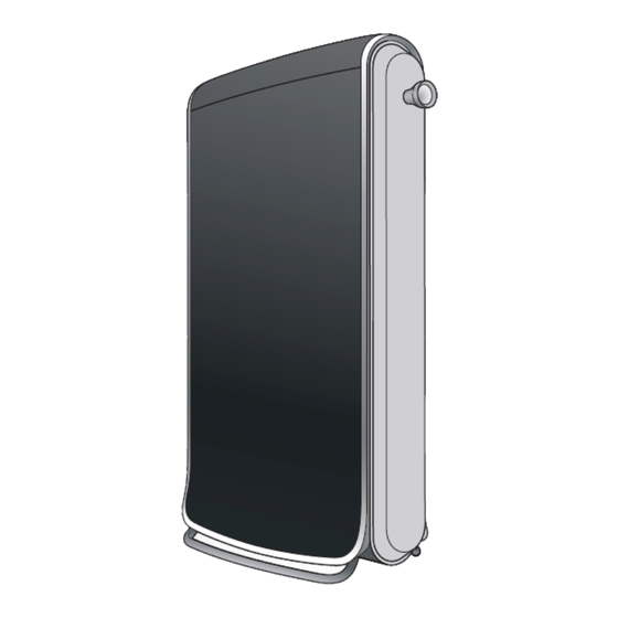
Page 4: Swash™ Clothing Care System
PRODUCT SPECIFICATIONS & WARRANTY INFORMATION SOURCES (inside back cover) SWASH™ Clothing Care System... -
Page 5: Section 1 - General Information
GENERAL INFORMATION Section 1: General Information This section provides general safety, parts, and information for the “SWASH™ Clothing Care System.” Q SWASH™ System Safety Q Model & Serial Number Label Q Tech Sheet Location Q SWASH™ System Q SWASH™ System Overview Q SWASH™... -
Page 6: Swash™ System Safety
IMPORTANT SAFETY INSTRUCTIONS WARNING: To reduce the risk of fire, electric shock, or injury to persons when using the SWASH™ system, follow basic precautions, including the following: n Read all instructions before using the SWASH™ system. n To reduce the likelihood of circuit overload, do not operate other high-wattage hardware (i.e. -
Page 7: Model & Serial Number Label
Model & Serial Number Label Model & Serial Number Label Location Figure 1 - Located on back panel of SWASH™ system Tech Sheet Location Tech Sheet Location Figure 2 - Located behind the back panel of SWASH™ system SWASH™ Clothing Care System... -
Page 8: Swash™ System
GENERAL INFORMATION SWASH™ System SWASH PODS™ BAY CONTROL PANEL ADJUSTABLE HANGER SLEEVE WRAPS DOOR RESERVOIR SMOOTHING CLIPS POCKET SMOOTHER SWASH PODS™ CUPS SWASH™ Clothing Care System... -
Page 9: Swash™ System Overview
Using the SWASH system is as easy as plugging it into a standard 120 VAC wall outlet. No water, plumbing, pipes, vents, special hook-ups, or professional installation assistance is needed. - Page 10 GENERAL INFORMATION Notes SWASH™ Clothing Care System...
-
Page 11: Section 2 - Operation
This section provides operational use and care information for the “SWASH™ Clothing Care System.” Q Connecting the SWASH™ System Q Buttons and Status Lights Q How Does the SWASH™ System Work? Q How to Use SWASH™ System Q Hanging Clothes Q Emptying the Reservoir Q Consumer Troubleshooting Q SWASH™... -
Page 12: Connecting The Swash™ System
OPERATION Connecting the SWASH™ System Connecting the SWASH™ System Plug your SWASH™ system into a standard grounded electrical outlet (110v). No plumbing, pipes, or vents needed. Figure 1 SWASH™ Clothing Care System... -
Page 13: Buttons And Status Lights
15 MINUTE BUTTON (EXTENDED CYCLE) extends drying time for heavier clothing ORANGE LIGHT flashes if you try to start SWASH™ system without a cup or if the door is not completely closed. If other lights are on with the orange light... -
Page 14: How Does The Swash™ System Work
How Does the SWASH™ System Work? The SWASH™ system works with a few key technologies. A superfine mist of the SWASH PODS™ formula is sprayed onto both sides of the hanging clothes. The smoothing clips (optional) pull clothes tight, and heat is circulated. -
Page 15: How To Use Swash™ System
“15” for extended cycle, or “X” to cancel. See page 3 for more information. Load 2. Load a SWASH POD™ cup in top of drawer and close drawer firmly (see Figure 4). Do not remove film from cup as it will get pierced when you push the drawer in. Only use SWASH PODS™... -
Page 16: Hanging Clothes
Smoothing clips aren’t needed for refreshing. You can get great results with minimal effort. For smoothing wrinkles, try experimenting with a few clips. IMPORTANT: The SWASH™ system is not recommend for silk, leather, velvet, suede, and fur. Some temporary spots may occur. If this happens, clean per clothing manufacturer’s instructions. - Page 17 Hang legs over the top of hanger first and then clip. Pull waist down and clip Pull a couple of smoothing clips through the to get the most area exposed to the SWASH PODS™ formula. hanger for shorts and skirts.
-
Page 18: Emptying The Reservoir
Emptying the Reservoir 3. Pull plug and empty out liquid in sink (see Figure 13). The SWASH™ system is designed to collect any excess mist for easy disposal. If the orange and blue lights are both flashing, you will need to empty the reservoir that collects the excess mist. -
Page 19: Consumer Troubleshooting
¾ Make sure door is closed properly. ¾ If SWASH™ system is plugged in, unplug it and plug it back in to reset. ¾ Make sure cup is loaded in bay. If cup is empty or missing, replace with new cup. - Page 20 OPERATION Notes 2-10 SWASH™ Clothing Care System...
-
Page 21: Section 3 - Component Access
COMPONENT ACCESS Section 3: Component Access This section provides service parts access, removal, and installation instructions for the “SWASH™ Clothing Care System.” n SWASH™ System Exploded Views n SWASH™ System Parts List n Removing the Rear Panel n Removing the Top Cover & Control Housing... -
Page 22: Swash™ System Exploded View
COMPONENT ACCESS SWASH™ System Exploded View NOTE: The SWASH™ System Exploded View was not available at the time of publication. Please refer to PartSmartweb Online Parts Catalog for product related parts information. This page is a place-holder for future revision. -
Page 23: Swash™ System Parts List
COMPONENT ACCESS SWASH™ System Part List NOTE: The SWASH™ System Parts List was not available at the time of publication. Please refer to PartSmartweb Online Parts Catalog for product related parts information. This page is a place-holder for future revision. -
Page 24: Removing The Rear Panel
COMPONENT ACCESS Removing the Rear Panel 4. Remove back cover. Using a T-20 TORX driver, remove the WARNING 9 screws securing the back cover to the SWASH system (see Figure 2). Electrical Shock Hazard Disconnect power before servicing. Replace all parts and panels before operating. -
Page 25: Removing The Top Cover & Control Housing
3. Lift the top up and away from the unit—starting from the 6. Remove control housing and set aside (see Figure 5). back (see Figure 2). Remove cover and set aside. Lift up cover and remove Figure 5 Figure 2 SWASH™ Clothing Care System... -
Page 26: Removing The User Interface
User Interface to the control bracket as illustrated in Figure 1. Pull UI Assembly forward over the Switch Harness door switch and remove from unit. Figure 1 - Dispensing System UI Harness Figure 1 - User Interface SWASH™ Clothing Care System... -
Page 27: Removing The Pump Assembly
4. Using a 1/4” nut driver, remove the two (2) screws securing the Thermistor to the control bracket (see Figure 1). Remove Thermistor from unit. Pump Harness Thermistor Figure 1 - Pump Assembly Wires Figure 1 - Thermistor SWASH™ Clothing Care System... -
Page 28: Removing The Door Assembly
COMPONENT ACCESS Removing the Door Assembly 3. Lay SWASH™ system on its side to access the bottom of WARNING the door assembly (see Figure 2). 4. Separate the lower slide from the door frame. Using a #2 Phillips screwdriver, remove the two (2) ‘side-mounted’... -
Page 29: Removing The Clips & Roller Assembly
Removing the Clips & Roller Assembly Removing the Clips & Roller Assembly 5. Set SWASH™ system upright. Using a #15 TORX driver, remove the two (2) screws securing the top door cover as illustrated in Figure 4. Remove cover to expose the upper 1. -
Page 30: Removing The Base Components
3-4 for location of reservoir.) 3. Remove the reservoir and set aside. 4. Lay SWASH™ system on its back (see Figure 1). 5. Using a 1/4” nut driver, remove the five (5) screws securing the bottom plate to the unit (see Figure 1). - Page 31 IMPORTANT: The fan motor and blower wheel cannot be replaced individually. The fan motor, blower wheel, and blower housing must be replaced as an assembly. Heater Connector Figure 4 Heater Assembly Blower Wheel Figure 5 Fan Motor Heater Screws (2) SWASH™ Clothing Care System 3-11...
-
Page 32: Removing The Side Panels
(see Figure 1). Set aside for reassembly. Figure 2 5. SWASH™ system with side panels removed (see Figure 4). NOTE: Two (2) sprayers on each side of cabinet. Lift up panel and remove... - Page 33 COMPONENT ACCESS Notes SWASH™ Clothing Care System 3-13...
- Page 34 COMPONENT ACCESS Notes 3-14 SWASH™ Clothing Care System...
-
Page 35: Section 4 - Diagnostics & Troubleshooting
DIAGNOSTICS & TROUBLESHOOTING Section 4: Diagnostics & Troubleshooting This section provides diagnostic, fault codes, and troubleshooting information for the “SWASH™ Clothing Care System.” n Safety First n Customer Troubleshooting n Customer Error Codes n Control Panel n Diagnostic Guide n Service Diagnostics... - Page 36 Any attempt to repair a major appliance may result in personal injury and property damage. The manufacturer or seller cannot be responsible, nor assume any liability for injury or damage of any kind arising from the use of this data sheet. SWASH™ Clothing Care System...
-
Page 37: Customer Troubleshooting
¾ Make sure door is closed properly. ¾ If SWASH™ system is plugged in, unplug it and plug it back in to reset. ¾ Make sure cup is loaded in bay. If cup is empty or missing, replace with new cup. -
Page 38: Control Panel
Right after powering up (plugging in the SWASH™ system), you n All tests/checks should be made with a VOM (volt-ohm- Right after powering up, you will have 30 seconds to press All tests/checks should be made with a VOM (volt-ohm-... -
Page 39: Service Diagnostic Functions
Service Diagnostic Functions (see page 4-4 for instructions) Right after powering up (plugging in the SWASH™ system), you will have 30 seconds to press the three different keys in any sequence three times within 10 seconds to place the SWASH™ system in service diagnostic mode. If entrance to service diagnostic mode is successful, the following functions will be available. -
Page 40: Fault / Error Codes
2. Verify the wire harness connection. Any open connection will create a resistance higher than 35.42kΩ and the error will remain. 3. Reset the ACU by unplugging the SWASH™ system for more than 5 seconds. 4. Enter the service diagnostics mode (see page 2) and review the operation of the thermistor. - Page 41 (185°F [85°C] max.) and humidity (95% non condensate). 3. Reset the SWASH™ system by disconnecting the power for more than 5 seconds. 4. Verify 5V output from the WIDE connector between lines P1-1 and P3-1 and the P19 connector.
-
Page 42: Troubleshooting Guide
NOTE: Possible Causes/Tests must be performed in the sequence show for each problem. WON’T POWER UP 1. Verify that the SWASH™ system is plugged into a working outlet and that there are no blown fuses or tripped circuit breakers. (buttons do not respond when pressed) 2. - Page 43 2. Disconnect the reservoir sensor switch. SWASH™ SYSTEM 3. Check the continuity (J3-3 to J3-4) in the reservoir sensor switch connector to the SWASH™system when the reservoir tray is inserted. If there is continuity, go to step 5. 4. If there is no continuity, replace the reservoir sensor switch.
-
Page 44: Wiring Diagram
DIAGNOSTICS & TROUBLESHOOTING FOR SERVICE TECHNICIAN’S USE ONLY For Service Technician Use Only WIRING DIAGRAM 4-10 SWASH™ Clothing Care System DO NOT REMOVE OR DESTROY... -
Page 45: Appliance Control Unit (Acu)
J3-4 Switch, GND J3-5 Thermistor (Temp 2) J3-6 Thermistor (Temp 1) CONNECTOR J2 (L1 and Heater) J2-7 Heater Assembly CONNECTOR P19 J2-12 L1 from plug (User Interface) P19-2 +5 VDC P19-3 Ref GND P19-4 DATA SWASH™ Clothing Care System 4-11... -
Page 46: User Interface (Ui) Assembly
Rigid PCB J1 - Appliance Control Unit Figure 3 - Rigid PCB UI CONNECTOR PIN-OUTS CONNECTOR J1 CONNECTOR P3 (Appliance Control Unit) (Flex PCB) J1-1 +5 VDC P3 - Ribbon Connector J1-2 DATA J1-3 Ref GND 4-12 SWASH™ Clothing Care System... -
Page 47: Strip Circuits
POD SENSOR SWITCH J3-4 RESERVOIR SENSOR SWITCH J3-3 RESERVOIR SWITCH THERMISTOR ACU BOARD ACU BOARD Thermistor ACU BOARD ACU BOARD THERMISTOR TEMP1 J3-6 J3-5 TEMP 2 10k Ω ∗ * Approximate value measured at room temperature SWASH™ Clothing Care System 4-13... - Page 48 DIAGNOSTICS & TROUBLESHOOTING Notes 4-14 SWASH™ Clothing Care System...
-
Page 49: Product Specifications
PRODUCT SPECIFICATIONS & WARRANTY INFORMATION SOURCES IN THE UNITED STATES: FOR PRODUCT SPECIFICATIONS AND WARRANTY INFORMATION CALL: PHONE: 1-866-333-4195 FOR TECHNICAL ASSISTANCE WHILE AT THE CUSTOMER’S HOME CALL: THE TECHNICAL ASSISTANCE LINE: 1-800-832-7174 HAVE YOUR STORE NUMBER READY TO IDENTIFY YOU AS AN AUTHORIZED IN-HOME SERVICE PROFESSIONAL FOR LITERATURE ORDERS (CUSTOMER EXPERIENCE CENTER): PHONE: 1-800-851-4605... - Page 50 SWASH™ Clothing Care System W10713431...
Need help?
Do you have a question about the SFF1001CSA series and is the answer not in the manual?
Questions and answers