Table of Contents
Advertisement
EN
Installation and Maintenance guide
GJPACW1V-15/20/30/40/60
GJPACW1-15/20/30
________________________________________________________________________________________________
Gullberg & Jansson AB | Smältaregatan 6 | SE - 263 39 Höganäs
Tel: +46 (0) 42 34 05 90 | Fax: +46 (0) 42 34 02 10 | E-mail: info@gullbergjansson.se | www.gullbergjansson.se
Advertisement
Table of Contents

Related Manuals for Gullberg Jansson GJPACW1V-30


Summary of Contents for Gullberg Jansson GJPACW1V-30
- Page 1 Installation and Maintenance guide GJPACW1V-15/20/30/40/60 GJPACW1-15/20/30 ________________________________________________________________________________________________ Gullberg & Jansson AB | Smältaregatan 6 | SE - 263 39 Höganäs Tel: +46 (0) 42 34 05 90 | Fax: +46 (0) 42 34 02 10 | E-mail: info@gullbergjansson.se | www.gullbergjansson.se...
- Page 3 Preface Congratulations on your purchase of a pool heat pump from Gullberg & Jansson AB. We hope it meets your expectations and provides you with many years of energy efficient heating. In this Installation and Maintenance Guide you can read how installation, operation, service and maintenance are to be performed to ensure correct function.
-
Page 5: Table Of Contents
Technical specification Checklist installation Guarantee conditions Connection key Chiller 300.2 Safety Regulations Wiring diagram One-phase connection Three-phase connection Installation GJPACW1V-15/20/30/40/60 Component placement Outline diagram Technical data Positioning the unit Dimensions and connections Set up GJPACW1-15/20/30 Distance to the pool Component placement... -
Page 7: General Information
The models GJPACW1-15/20/30 and outdoor temperature and the temperature of the pool GJPACW1V-15/20/30/40/60 are a range of specifically water. The heat pump can be seen to perform with different developed air/water heat pumps designed for energy efficiency during different parts of the year depending on efficient heating of swimming pools or spa pools. -
Page 8: Component Part And Accessories
If the heat pump is tilted during installation or draining this GJPACW1-15/20/30 and GJPACW1V-15/20/30/40/60 are should be done with care and for the shortest time possible. designed for reliable operation and a long life. If a fault... -
Page 9: Checklist Installation
General information Checklist installation Guarantee conditions The following checklist provides a general description of how The component parts of the system must be transported, the installation is carried out. stored, installed and used in accordance with the provisions set out in the manual. Place the heat pump on a firm and horizontal surface. -
Page 11: Installation
Installation A comprehensive installation description is provided in this chapter. This chapter is primarily intended for installation engineers, but can also be read by the end user to increase his/her knowledge. Outline diagram Chlorinator POOL Sand filter Circulation pump Refer to the labels on the unit before connecting the inlet and outlet. Positioning the unit Set up The pool heat pump will work ideally under the following... -
Page 12: Distance To The Pool
Installation Distance to the pool The pool heat pump is normally installed in connection to the pool’s purification system to minimise pipe routing. If the pipes are insulated heat loses will be minimal provided that the overall pipe length is less than 30 metres (pool water in and pool water return). - Page 13 Installation Press ON/OFF on the display, the unit should start after a few seconds. After a few minutes, check that the exhaust air is colder than the outdoor air temperature (5-10 ºC). Stop the pool’s circulation pump and make sure that the pool heat pump stops automatically.
-
Page 15: Use And Operation
Use and operation Description of LED controls within 5 seconds the LED display shows the incoming water temperature. When the unit is in standby mode, it shows the current time. A description of the LED display is given below. All parameters are set at the factory and do not need to be How to change operating parameters adjusted before start up. -
Page 16: How You Select The Operating Mode
Use and operation Defrosting Defrosting Defrosting Heating Heating Heating Cooling Cooling Cooling Timer Timer Timer Timer Timer Timer Parameter 7: Automatic restart on Parameter 8: (0 = Cooling mode / 1 Parameter 9: External pump. (0 = power failure. (0 = No / 1 = Yes) = Heating mode or cooling mode / Always running / 1 = Running at 2 = Not used / 3 = Heating mode) -
Page 17: Setting The Time
Use and operation Setting the time Press CLOCK. Current time is shown in the display. Press CLOCK. The hours will start blinking, and can be adjusted with the arrows. Defrosting Heating Cooling Press CLOCK again. The minutes will start blinking, and can be adjusted Timer Timer with the arrows. -
Page 19: Maintenance, Service And Fault Tracing
Maintenance, service and fault tracing Winter drainage with winter drainage. Flush the heat exchanger using e.g. a garden hose and drain thoroughly. This will reduce the risk of chlorine deposit build up. It is extremely important to remember to winter drain the machine before winter storage! The guarantee does Check the power supply and cable connections regularly. -
Page 20: Fault Charting Table
Maintenance, service and fault tracing Fault charting table Operating disturbance Cause Action Press the ON/OFF button. The heat pump is in standby mode. Change the operating mode to heating The heat pump is in cooling mode. mode as set out in the section 3. The heat pump is too small for the Larger heat pump required. -
Page 21: Technical Specification
Technical specification Connection key Chiller 300.2 CHILLER 300.2 Designation Description AC-N Neutral conductor (230 VAC) AC-L Phase conductor (230 VAC) COMP1 Control signal to compressor relay (230 VAC) COMP2 Control signal to compressor relay (230 VAC) VAL1 Control signal to four way valve (230 VAC) VAL2 Control signal to four way valve (230 VAC) Control signal to fan motor (230 VAC) -
Page 22: Wiring Diagram
Technical specification Wiring diagram One-phase connection GJPACW1(V)-15/20/30/40 ONLY FOR GJPACW1(V)-15 ONLY FOR GJPACW1(V)-20/30/40 SOFT START HEATER CHILLER 300.2 ROOMT PIPE2 PIPE1 OUTWT INWT RED BLU EXT. COND. TO POWER SUPPLY 230 VAC 230 VAC REMARKS: C1: COMPRESSOR CAPACITOR C2: FAN MOTOR CAPACITOR Wire Controller CM: COMPRESSOR COND: EVAPORATOR TEMP. -
Page 23: Three-Phase Connection
Technical specification Three-phase connection GJPACW1(V)-30/60 PROTECT CHILLER 300.2 ROOMT PIPE2 PIPE1 OUTWT INWT L1 L2 29 30 Wire Controller L1 L2 L3 N REMARKS: C: FAN MOTOR CAPACITOR RDBLK WH RD BLK WH BLU CM: COMPRESSOR COND: EVAPORATOR TEMP. SENSOR L1 L2 L3 N DT: DISCHARGE TEMP. -
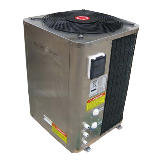
Page 24: Gjpacw1V-15/20/30/40/60
Technical specification GJPACW1V-15/20/30/40/60 Component placement Component placement Protective net Chiller 300 Evaporator Electronic box - lid Electronic box Stainless steel casing - front Fan motor bracket Flow switch Fan motor PVC through-connection Impeller PVC-cross Stainless steel casing - top PVC-plate (80×80 mm) -
Page 25: Technical Data
Technical specification Technical data Model GJPACW1V-15 GJPACW1V-20 GJPACW1V-30 GJPACW1V-40 GJPACW1V-60 Heating output 13.8 18.2 Input power Heating capacity 20 - 35 30 - 50 40 - 80 60 - 110 80 - 150 Operating voltage 230 VAC 1-phase 50 Hz... -
Page 26: Gjpacw1-15/20/30
Technical specification GJPACW1-15/20/30 Component placement Component placement Stainless steel casing - top Compressor Protective net - back High pressure switch Stainless steel casing - left Low pressure switch Fan motor bracket Flow switch Protective net - left Stainless steel casing - right Fan motor LED-controller Impeller... -
Page 27: Technical Data
Technical specification Technical data Model GJPACW1-15 GJPACW1-20 GJPACW1-30 Heating output 13.8 Input power Heating capacity 20 - 35 30 - 50 40 - 80 Operating voltage 230 VAC 1-phase 50 Hz 400 VAC Operating current 5.23 7.50 11.4 4.47 Fuse size Compressor Rotary compressor Scroll... -
Page 29: Appendices
Appendices Questions and answers How long will it take for the pool to be warm? Answer: You usually calculate with about a 1-2 degree How do I set the temperature? increase in the temperature per day. However, if you require faster heating you can always choose a larger model.
Need help?
Do you have a question about the GJPACW1V-30 and is the answer not in the manual?
Questions and answers