
Related Manuals for Everest EGC 150 MA / 250


Summary of Contents for Everest EGC 150 MA / 250
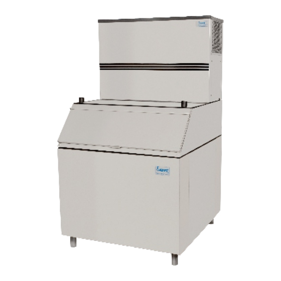
- Page 1 TECHNICAL MANUAL ICE CUBE MACHINES SINCE 1966 EGC 50 A EGC 75 A EGC 100 A / 150 A EGC 150 MA EGC 150 MA / 140 EGC 150 MA / 250 EGC 300 MA / 250 VALID FOR UNITS PRODUCED SINCE SEPTEMBER/2015...
-
Page 2: Table Of Contents
INDEX INTRODUCTION/TECHNICAL FEATURES........................ MODELS AND POSSIBLE SETTINGS........................IMPORTANT INFORMATION..........................EQUIPMENT INSTALLATION..........................TYPICAL INSTALLATION DIAGRAM........................MAIN COMPONENTS............................OPERATING PRINCIPLE............................1 - CLEANING CYCLE............................2 - ICE FORMATION CYCLE........................... 3 - ICE FORMATION CYCLE........................... 4 - OPERATION OF THE TANK THERMOSTAT......................SCHEDULED MAINTENANCE..........................NAME OF MAIN COMPONENTS........................... -
Page 3: Introduction/Technical Features
INTRODUCTION DEAR USER: Everest Refrigeração Indústria e Comércio Ltda, congratulates you for choosing to purchase your Automatic Ice Cube Machine. In our industry, everything was done to make sure that your machine will have the best performance for many years to come. Your collaboration is required by, first reading this manual carefully, and then using it as recommended below. - Page 4 MIN. SECTION OF DIMENSÕES MODEL MODEL COMPRESSOR MODEL MODELO THE WIRES (mm2) (A/L/P) cm TECUMSEH AE4430Y (AE-540) 50A - 127V EMBRACO FFI 8.5 HBK 50A - 220V 75A - 127V 75A - 220V 100A TECUMSEH AE4450Y (AE-660) 100A - 127V 150A 150MA 100A - 220V...
-
Page 6: Important Information
IMPORTANT INFORMATION This equipment is not intended for use by people - including children - with reduced physical, sensory or mental capacity, or by people with lack of experience and knowledge, unless they have received instructions regarding the use of the equipment or they are under the supervision of a person responsible for their safety. It is recommended that children be supervised to ensure that they do not play with the equipment. -
Page 7: Typical Installation Diagram
TYPICAL INSTALLATION DIAGRAM 1) Ice cube machine. 2) Female electrical outlet. 3) Water supply valve. 4) Water filter. 5) Hydraulic connection filter / water inlet hose. 6) Flexible water inlet hose. 7) Flexible water outlet hose (for sewage entry point). Notes: 1 •... -
Page 8: Main Components
MAIN COMPONENTS A • Evaporator (20): Made of copper with nickel finishing, it has vertical cube makers around which the ice cubes are formed. B • Gear motor (60): It moves the plastic trough (35). C • Micro gear motor (57): It moves the finned axis in order to stir the water, improving the ice quality. -
Page 9: Operating Principle
OPERATING PRINCIPLES 1 - CLEANING CYCLE 1.1 - Initialization Every time the machine is energized (connected to the power grid, switched on again by the tank's thermostat (61) or after a power surge), the cleaning cycle for the plastic trough (35) and evaporator (20) starts up. The signaling LEDs - LD1 (maintenance), LD2 (water shortage) - for the circuit board (62) and the LED board (68), light up for a period of 02 seconds, in order to inform the start-up of the system's operation. -
Page 10: Scheduled Maintenance
SCHEDULED MAINTENANCE Before starting maintenance, unplug the machine and remove the machine's cover (1), except for the EGC-150MA model. For the EGC-150MA model: Remove the right side plate (16), loosen the fixation screws, open the frontal lid or the right side plate (16). 1 •... -
Page 11: Name Of Main Components
NAME OF MAIN COMPONENTS COVER PLASTIC TROUGH SUPPORT ASSEMBLY FRONT COVER EGC-50Atf 5A/100A/150A FINNED AXIS' BEARING LEVER-ARM REDUCER PLASTIC GRATING EGC-50A/75A/100A/150MA SPRING PIN WATER COLLECTOR OF THE EGC-50A TANK LEFT PANEL OF CYLINDER HEAD ICE TANK HOUSING MICRO GEAR MOTOR CONNECTION BUSHING EGC-50A COOLING UNIT BASE FAN MICROSWITCH REAR GRATING EGC-A... -
Page 12: Overview Egc-50A
OVERVIEW EGC-50A COVER COOLING SYSTEM... -
Page 13: Overview Egc-75A, Egc-100A And Egc-150A
OVERVIEW EGC-75A, EGC-100A AND EGC-150A In the EGC-150A model, there are two compressors and two fans. -
Page 14: Overview Egc-150Ma
OVERVIEW EGC-150MA... -
Page 15: Cooling System Egc-50A, Egc-75A, Egc-100A And Egc-150A
COOLING SYSTEM EGC-50A, EGC-75A, EGC-100A AND EGC-150A COOLING SYSTEM EGC-150MA... -
Page 16: Electrical Electronic Part
ELECTRICAL/ELECTRONIC PART... -
Page 17: Trough Displacement System
TROUGH DISPLACEMENT SYSTEM TROUGH DISPLACEMENT ARM ASSEMBLY... -
Page 18: Wiring Diagram Egc-50A, Egc-75A, Egc-100A-220V
ELETRICAL DIAGRAM EGC-50A, EGC-75A, EGC-100A - 127V MICRO GEAR MOTOR THERMAL PROTECTOR WATER END OF CYCLE LEVEL MICROSWITCH SENSOR CIRCUIT BOARD START-UP CAPACITOR REDUCER RELAY TANK PLUG THERMOSTAT GAS VALVE FUSE HOLDER TRANSFORMER FAN MICROSWITCH WATER VALVE ELETRICAL DIAGRAM EGC-50A, EGC-75A, EGC-100A - 220V MICRO GEAR MOTOR THERMAL PROTECTOR... -
Page 19: Wiring Diagram Egc-50A, Egc-75A, Egc-100A-127V
ELECTRICAL DIAGRAM EGC-150A, EGC-150MA - 220V MICRO GEAR MOTOR THERMAL PROTECTOR WATER LEVEL END OF CYCLE SENSOR MICROSWITCH START-UP CAPACITOR CIRCUIT THERMAL BOARD PROTECTOR REDUCER START-UP CAPACITOR WATER VALVE RELAY GAS VALVE TANK THERMOSTAT GAS VALVE FAN MICROSWITCH FUSE HOLDER ELECTRICAL DIAGRAM FOR TECUMSEH COMPRESSORS THERMAL PROTECTOR START-UP... -
Page 20: Equipment Failure Management
EQUIPMENT FAILURE MANAGEMENT The circuit board (62) is equipped with a program that monitors the operation of the ice machine. When there is an anomaly in this function, it controls the main components (gear motor (60), micro gear motor (57), gas solenoid valve (28) and water solenoid valve (63)), in order to resolve the aforementioned anomaly or protect the equipment in general. -
Page 21: Symptom Water Shortage Or Low Water Flow Rate
1 - SYMPTOM WATER SHORTAGE OR LOW WATER FLOW RATE Probable causes: • Water shortage in the supply network (reversible defect). • Decrease in water pressure from the supply network (reversible defect). • Saturated water filter (irreversible defect). • Water solenoid valve (63) not working (irreversible defect). The circuit board (62) waits for 15 minutes for the water level to touch the mobile water sensor (55). -
Page 22: Symptom: Plastic Trough Do Not Descends
2 - SYMPTOM PLASTIC TROUGH CANNOT BE LOWERED Probable causes: • Gear motor (60) not working (irreversible defect). • Ice crystals attaching the plastic trough (35) to the evaporator (20) (reversible defect). • Upper reed switch (54) short circuited (irreversible defect). When the circuit board (62) switches on the gear motor (60) to lower the trough (35), it monitors whether the upper reed switch (54) triggers in up to 5 seconds. -
Page 23: Symptom: By-Pass Cycle Over 2 Minutes
4 - SYMPTOM: BY-PASS CYCLE OVER 2 MINUTES Probable causes: • By-pass gas solenoid valve (28) not (irreversible defect). • End of cycle microswitch (59) is stuck (irreversible defect). During the ice detachment cycle, after 45 seconds of by-pass, the circuit board (62) switches on the micro gear motor (57) for 5 seconds and checks whether the axis is still blocked by any ice cube. -
Page 24: Symptom: Trough (35) Is Suspended, But Does Not Reach The Highest Point
6 -SYMPTOM: TROUGH (35) RISES, BUT DOES NOT ACHIEVE THE HIGHEST POINT Probable causes: • Damage to the displacement system (reversible defect). • Gear motor (60) not working (irreversible defect). • Ice cubes inside the plastic trough (35) (reversible defect). •... -
Page 25: Analysis Of Defects
If the anomaly is repeated 5 consecutive times, the circuit board (62) positions the plastic trough (35) at the lowest point, switches on the red LED light and waits for 10 minutes. After 10 minutes, the circuit board (62) switches off the red LED light and switches on the gas solenoid valve (28) for 45 seconds, cleaning the evaporator (20) and preventing the accumulation of ice crystals in it, and starts another attempt. -
Page 26: Water Trough Goes Up And Down Continuously
2.3 - WATER TROUGH GOES UP AND DOWN CONTINUOUSLY CORRECTION PROBABLE CAUSES Circuit board not working. (62) Change the circuit board. (62) 2.4 - CONTINUOUS ENTRANCE OF WATER IN THE TROUGH PROBABLE CAUSES CORRECTION Water valve (63) does not close (yellow LED on). Change the water valve. -
Page 27: Machine Working But Does Not Produce Ice
2.6 - MACHINE WORKING BUT NOT PRODUCING PROBABLE CAUSES CORRECTION Circuit board not working. (62) Change the circuit board. (62) No water enters the plastic trough (35) (yellow LED on). See item water shortage or low water flow (p. 20). Loss of refrigerant gas. -
Page 28: Displacement System And Trough
3.1 - DISPLACEMENT SYSTEM AND TROUGH The plastic trough (35) has two stopping points, which are: Highest Point Lowest Point In case there's the need to regulate these points (due to plastic trough (35) replacement, upper or lower reed switch (54 and 58), magnet displacement system, etc.), proceed as follows: A •... -
Page 29: Axis Unsettled
If you wish to adjust the water level, use the following procedure: 1º • Stop the movement of the finned axis (50), which will cause the micro gear motor to stop (57). 2º • Suspend or lower the mobile sensor (55), according to the desired water level. 3º... -
Page 30: Circuit Board
D • Remove the spacers (30) and fins (29) and replace the finned axis (50). E • During the assembly, mount the spacers (30) and fins (29), placing them between the rows of the evaporator (20) and push from the left side. Verify if the axes of the evaporator (20), the stopper of the plastic trough (21), the start-up assembly of the plastic trough (48) and the finned axis (50) are in the correct position and tighten the two nuts on the panel. -
Page 31: Circuit Board Does Not Control Any Component
The circuit board (62) controls various components, such as the gas by-pass solenoid valve (28) gear motor (60), water solenoid valve (63) and micro gear motor (57). And it receives information to perform the functions of other components, such as the end of cycle microswitch (59), lower reed- switch (58), upper reed-switch (54) and mobile water sensor (55). -
Page 32: B- Components Controlled By The Electronic Board
Lower reed-switch (58): • To check the perfect functioning of the lower reed-switch (58), proceed similarly as the upper reed- switch (54) test, but checking the continuity of the terminal (E) of the circuit board (62) with the aid of an ohmmeter. -
Page 33: Inoperative Water Valve
3.5 - INOPERATIVE WATER VALVE Check if there is voltage (220V) on the terminals of the water valve (63), if not, check for voltage (220V) on the terminals (A) of the circuit board (62). If confirmed that there is no voltage in the circuit board, repair the electrical supply harness of the valve. -
Page 34: Gas Charge/Replacement Of The Cooling Compressor
3.6 - GAS LOAD / REPLACEMENT OF THE COOLING COMPRESSOR Check the following items when replacing the compressor (23): A • The TECUMSEH AE-4430Y (AE-540) or the EMBRACO FF 8.5HBK should be used for the EGC-50A Ice Machine and the TECUMSEH AE-4450Y (AE-660) or the EMBRACO FFI 12HBX for the EGC-75A, 100A, 150A and 150MA Ice Machines. - Page 35 E • A burnt compressor (23) can be caused by many factors, so when replacing the compressor (23), we should observe several items so as not to endanger the service life of the new compressor. • Clean the condenser gas (25) because bad gas condensation leads to high working pressure (18kgf/cm2 = 260psig), raising the electric current (higher energy consumption) and the operating temperature of the compressor's (23) electric motor.
- Page 37 EVEREST REFRIGERAÇÃO IND. E COM. LTDA. RESERVES THE RIGHT TO MAKE CHANGES TO ITS EQUIPMENT WITHOUT PRIOR NOTICE.
- Page 38 MANUFACTURER'S TECHNICAL ASSISTANCE 0800 0240332 / assistec@everest.ind.br Suggestions, information and complaints: Call 0800 024 0332, send a FAX: (21) 2591-4798 or via e-mail everest@everest.ind.br. To facilitate customer assistance, please have the machine model, invoice and serial number at hand. EVEREST REFRIGERAÇÃO INDÚSTRIA COMÉRCIO LTDA.
Need help?
Do you have a question about the EGC 150 MA / 250 and is the answer not in the manual?
Questions and answers