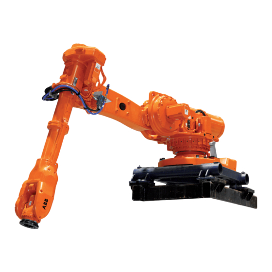
Summarization of Contents
Safety
Introduction
Provides an overview of safety information in the manual, divided into general and specific safety aspects.
General safety information
Covers general safety aspects applicable to all service work on the robot, including validity and responsibility.
Safety related instructions
Details specific dangers that may arise from performing work, including danger levels and safety signals.
Installation and commissioning
Introduction
Provides information for installing the robot at the working site, including technical data.
Unpacking
Covers pre-installation procedures, robot weights, loads on foundation, and operating conditions.
On-site installation
Details procedures for on-site installation, including lifting, securing, and fitting equipment.
Restricting the working range
Describes how to install hardware to restrict the robot's working range for safety.
Maintenance
Maintenance schedule and expected component life
Details maintenance intervals and expected component life for robot maintenance.
Inspection activities
Provides procedures for inspecting various components like gearbox oil levels and cable harnesses.
Replacement/changing activities
Covers procedures for changing gearbox oil, replacing components, and lubrication tasks.
Service Information System, M2000
Describes how to use the Service Information System (SIS) for robot maintenance scheduling.
Repair
General procedures
Includes general procedures like performing leak-down tests and mounting instructions for bearings and seals.
Complete robot
Details procedures for replacing major robot components like cable harnesses and arm systems.
Upper and lower arm
Covers replacement procedures for components like the turning disk, wrist unit, and lower arm.
Frame and base
Details replacement procedures for the SMB unit and brake release unit.
Motors
Provides procedures for replacing motors on various axes (1, 2, 3, 4, 5, 6).
Gearboxes
Covers replacement procedures for gearboxes on axes 1, 2, 3, 4, 5, and 6.
Calibration information
Introduction
Provides general information about calibration methods and procedures.
Calibration methods
Describes different calibration types like Standard, Absolute Accuracy, and Levelmeter Calibration.
Calibration scales and correct axis position
Specifies calibration scale positions and correct axis positions for robot models.
Updating revolution counters
Details how to update revolution counter values for robot axes using the pendant or FlexPendant.
Checking the calibration position
Describes methods to check the robot's calibration position using MoveAbsJ or Jogging window.
Reference information
Applicable Safety Standards
Lists general and robot cell safety standards applicable to robot operation and design.
Unit conversion
Provides a converter table for common units used in the manual.
Screw joints
Details how to tighten various types of screw joints and specifies torque values.
Weight specifications
Defines how component weights are specified and recommends using lifting equipment for heavy parts.
Standard toolkit
Lists the standard tools required for service activities, defined in a table.
Special tools
Specifies special tools required for service procedures and lists tools that may be rented.
Lifting equipment and lifting instructions
Explains that lifting equipment specifications are in separate instructions.
Spare part / part list
Introduction
States that this chapter specifies all spare parts and replacement articles of the robot.
Spare part list
Specifies all articles considered spare parts of the robot.
Part list
Provides an overview of rebuilding parts and their applicability to different robot versions.
Exploded views
Introduction
States that this chapter contains detailed views of robot components, specified by item numbers.
Base incl. Frame
Shows an exploded view of the robot's base and frame.
Frame - lower arm 1
Provides an exploded view of the robot's frame and lower arm assembly.
Frame - lower arm 2
Shows an exploded view of the robot's frame and lower arm assembly.
Upper arm
Provides an exploded view of the robot's upper arm.
Wrist complete
Shows an exploded view of the robot's complete wrist unit.
Circuit Diagram
Introduction
Includes circuit diagrams for the robot, noting different cable harness designs.
Validity of circuit diagram 3HAC 13347-1
Details how to determine if a circuit diagram is valid based on the cable harness article number.
Validity of circuit diagram 3HAC 025744-1
Explains how to check the validity of a circuit diagram based on the cable harness article number.
Connection point location
Illustrates connection point locations on various robot axes.
Legend
Provides a legend for symbols used in the circuit diagrams.


Need help?
Do you have a question about the IRB 6650S - 90/3.9 and is the answer not in the manual?
Questions and answers