Table of Contents
Advertisement
SERVICE
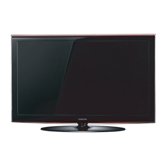
TFT-LCD TV
LE32A65*A/LE37A65*A/LE40A65*A/LE46A65*A
/LE52A65*A/LE32A616A/LE40A616A
Refer to the service manual in the GSPN (see the rear cover) for the more information.
LCD-TV
Chassis
: N46A
Model
: LE32A65*A
LE37A65*A
LE40A65*A
LE46A65*A
LE52A65*A
LE37A616A
LE40A616A
Manual
1. Precautions
2. Product specifications
3. Disassembly and Reassembly
4. Troubleshooting
5. Exploded View & Part List
6. Wiring Diagram
Contents
Advertisement
Table of Contents

Summarization of Contents
Precautions
Safety Precautions
Follow safety, servicing, and ESD precautions to prevent electrical shock and component damage.
Servicing Precautions
Read and follow safety precautions before servicing; handle components carefully to avoid damage.
Electrostatically Sensitive Devices (ESD) Precautions
Techniques to reduce component damage from static electricity, including body grounding and handling.
Installation Precautions
Safety guidelines for product installation, including handling and ventilation requirements.
Product Specifications
Feature & Specifications
Details on digital TV, connectivity, brightness, contrast, response time, and other key features.
Movie Plus: MJC(Motion Judder Cancellation)
Explanation and block diagram of Movie Plus technology for motion judder cancellation.
Spec Comparison to the Old Models
Comparison table detailing specifications of Amber and Peony models against older versions.
Accessories
List of included accessories with their respective product codes and remarks.
Disassembly and Reassemble
Disassembly - Stand
Step-by-step instructions for disassembling the LCD TV, including screw removal and stand detachment.
Disassembly - Rear Cover
Steps for removing the rear cover and fan, illustrated with pictures.
Disassembly - Boards and Speakers
Instructions for removing the IP and main boards, speakers, and inlet socket screws.
Disassembly - Stand and AV Assembly
Procedures for removing stand bracket components and side AV assemblies.
Disassembly - Bracket Screws
Steps for removing bracket screws for different screen sizes and a caution regarding pressure.
Disassembly - Panel
Procedure for removing the panel screws and reassembly notes.
Troubleshooting
Troubleshooting - General Checks
General troubleshooting steps for cable connections, power input to boards, and picture noise analysis.
Troubleshooting - No Power
Diagnostic flowchart for troubleshooting no power issues, checking LEDs, relays, fuses, and voltages.
Troubleshooting - No Video (Analog PC signal)
Troubleshooting steps for no picture with analog PC input, checking PC source, cables, and LVDS signals.
Troubleshooting - No Video (HDMI - Digital Signal)
Diagnostic steps for no video issues with HDMI input, checking HDMI source, cable, and digital data.
Troubleshooting - No Video (Tuner_CVBS)
Troubleshooting for no video from tuner or CVBS signal, checking RF signal, voltage, and digital data.
Troubleshooting - No Picture (Video_CVBS)
Procedure for diagnosing no picture with Video_CVBS signal, focusing on signal appearance and harness checks.
Troubleshooting - No Picture (S-VIDEO_Y,C)
Troubleshooting steps for no picture with S-Video input, checking source signals and cable connections.
Troubleshooting - No Sound
Diagnostic steps for troubleshooting no sound issues, checking RF source and audio signals.
Defect Analysis ahead of models
Analysis of common defective images and symptoms, including LVDS connector issues.
Alignments and Adjustments
General instructions and precautions for performing alignments and adjustments on the LCD TV.
Factory Mode Adjustments
Procedures for entering factory mode and performing panel checks, including label rating verification.
Factory Data
Details on factory data items including Option Table, WB Adjust, and Information.
White Balance Calibration
Detailed procedure for white balance calibration, including color calibration settings and equipment.
Servicing Information
Information regarding USB firmware upgrades and contact details for Samsung support.
EDID Self-Write Method
Procedure for EDID self-write, including factory settings for HDMI versions and panel types.
Exploded View & Part List
LE32A65*A Exploded View
Exploded view diagram illustrating the assembly of the LE32A65*A model.
LE32A65*A Parts List
List of parts for the LE32A65*A model, including location, code, description, and quantity.
LE37A65*A/ LE37A616A Exploded View
Exploded view diagram for LE37A65*A and LE37A616A models.
LE37A65*A Parts List
Parts list for LE37A65*A model, detailing components and their specifications.
LE37A616A Parts List
Parts list for LE37A616A model, including codes, descriptions, and quantities.
LE40A65*A/ LE40A616A Exploded View
Exploded view diagram for LE40A65*A and LE40A616A models.
LE40A65*A Parts List
Parts list for LE40A65*A model, detailing components and their specifications.
LE40A616A Parts List
Parts list for LE40A616A model, including codes, descriptions, and quantities.
LE46A65*A Exploded View
Exploded view diagram for LE46A65*A model.
LE46A65*A Parts List
Parts list for LE46A65*A model, detailing components and their specifications.
LE52A65*A Exploded View
Exploded view diagram for LE52A65*A model.
LE52A65*A Parts List
Parts list for LE52A65*A model, including codes, descriptions, and quantities.
Wiring Diagram
Wiring Diagram
Schematic diagram illustrating the wiring connections within the LCD TV.
Wiring Picture
Photographic illustration showing the physical location of internal wiring and components.
Connector Functions
Description of the function for each major connector and potential defective symptoms.
Cables
Visual catalog of various cables used in the assembly, with part numbers and dimensions.


Need help?
Do you have a question about the LE40A616A and is the answer not in the manual?
Questions and answers