Table of Contents
Advertisement
ELECTRONICS
This Service Manual is a property of Samsung Electronics Co .,Ltd.
Any unauthorized use of Manual can be punished under applicable
International and/or domestic law.
© Samsung Electronics Co., Ltd. AUG. 2004
Printed in Korea
AK82-00661A
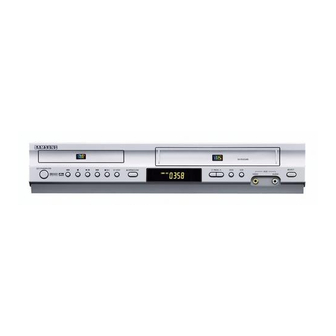
DVD-VCR COMBINATION
Chassis : Kaiser
SV-DVD340P/DVD440P
SV-DVD541P/DVD546P
SV-DVD641P/DVD645P
SERVICE
If you want to know additional information which is not included on this Service Manual, please refer to the
SV-DVD440 Training Manual (AK82-00513A).
DVD-VCR COMBINATION
SV-DVD645P/DVD546P
AUX
SV-DVD641P/DVD541P/DVD440P
AUX
SV-DVD340P
Manual
CONTENTS
1. Precautions
2. Alignment and Adjustment
3. Exploded Views and Parts List
4. Electrical Parts List
5. Block Diagram
6. Schematic Diagrams
Advertisement
Chapters
Table of Contents

Related Manuals for Samsung SV-DVD645P


Summarization of Contents
Precautions
Safety Precautions
Essential safety checks, leakage, and insulation resistance tests.
Servicing Precautions
General servicing practices, component replacement, and insulation checks.
ESD Precautions
Guidelines for handling electrostatically sensitive devices.
Optical Pick-up Handling
Specific procedures for protecting optical pick-ups from static electricity.
Pick-up Disassembly and Reassembly
Step-by-step instructions for disassembling and reassembling the pick-up unit.
Alignment and Adjustments
VCR Adjustment
Details X-Point, Head Switching, and NVRAM setting adjustments for VCR.
DVD Adjustment
Covers DVD adjustments like skew and test point locations.
VCR Mechanical Adjustment
Procedures for tape transport system and reel torque adjustments.
Exploded View and Parts List
Cabinet Assembly
Exploded diagram and parts list for the unit's cabinet components.
VCR Mechanical Parts (Top Side)
Exploded view and parts list for VCR mechanical components on the top side.
VCR Mechanical Parts (Bottom Side)
Exploded view and parts list for VCR mechanical components on the bottom side.
DVD Mechanical Parts
Exploded diagram and parts list for the DVD mechanical components.
Schematic Diagrams
SMPS Schematic
Power supply schematic showing components and connections.
Power Drive Schematic
Schematic detailing the power drive circuitry and connections.
Display/Function Schematic
Diagram illustrating the display and function control circuits.
System Control/Servo Schematic
Schematic for the system control and servo mechanisms.
A/V Schematic
Schematic diagram for the Audio/Video processing circuits.
Hi-Fi Schematic
Diagram of the Hi-Fi audio processing circuitry.
A2/NICAM Schematic
Schematic for the A2/NICAM audio decoding circuits.
SECAM (Option) Schematic
Diagram showing the SECAM optional video decoding circuits.
TM Schematic
Schematic for the TM (Tuner/Modulator) circuitry.
Input-Output Schematic
Diagram illustrating input/output connections and related circuits.
DVD AV Decoder Schematic
Schematic for the DVD AV decoder IC and its connections.
DVD Servo Schematic
Diagram of the DVD servo control circuitry.
DVD Audio/VIDEO Schematic
Schematic for the DVD audio and video output circuits.
Need help?
Do you have a question about the SV-DVD645P and is the answer not in the manual?
Questions and answers