Table of Contents
Advertisement
WA002<Rev.001>
B53-0894-00
SERVICE MANUAL
10
2011
KDC-202U, KDC-252U, KDC-3054UG, KDC-3054UR,
KDC-3054URY, KDC-316UR, KDC-3254URY, KDC-3354UGY,
KDC-3454UQ, KDC-3554UGM, KDC-3554URM, KDC-4054UB,
KDC-4054UR, KDC-MP152U, KDC-MP2052U, KDC-MP252U,
Tuner setting adjustment after replacing E2PROM
After replacing E2PROM (IC771 on ELECTRIC UNIT), tuner
setting adjustment is needed.
The adjustment is that to perform the "TUNER Setting
Adjustment Mode" in the TEST MODE.
Illustration is KMR-350U
M. sleeve assy
(GE34826-001A)
Tap screw (2x8)
(QYSPSF2008MA)
COPYRIGHT © 2011 JVC KENWOOD Corporation
B53-0894-00
SERVICE MANUAL
CD RECEIVER
KDC-U3553, KMR-350U
DC cord
(QAM13xx-001)
Screw set
(GE40536-001A)
COPYRIGHT © 2011 JVC KENWOOD Corporation
TDF SPARE-PANEL
MAIN UNIT NAME TDF PARTS No.
KDC-202U
KDC-252U
KDC-3054UG
KDC-3054UR
KDC-3054URY
KDC-316UR
KDC-3254URY
KDC-3354UGY
KDC-3454UQ
KDC-3554UGM
KDC-3554URM
KDC-4054UB
KDC-4054UR
KDC-MP152U
KDC-MP252U
KDC-U3553
KMR-350U
DC cord
Carrying case
(QAM13xx-001)
(GE40521-001A)
Hook
(GE40578-001A) x2
This product complies with the RoHS directive for the European market.
Y33-3530-10
Y33-3520-10
Y33-3532-72
Y33-3532-71
Y33-3532-74
Y33-3532-73
Y33-3532-75
Y33-3532-77
Y33-3532-76
Y33-3530-23
Y33-3530-22
Y33-3522-71
Y33-3522-72
Y33-3530-11
Y33-3520-12
Y33-3530-21
Y33-3520-11
Remocon unit (RC-405)
(QAL1303-001)
Hard case assy
Trim plate
(GE34332-002A)
(GE20xxx-xxxA)
This product uses Lead Free solder.
No.WA002<Rev.001>
TDF NAME
TDF-1220D
TDF-1225D
TDF-3054UG
TDF-3054UR
TDF-3054URY
TDF-316UR
TDF-3254URY
TDF-3354UGY
TDF-3454UQ
TDF-3554UGM
TDF-3554URM
TDF-4054UB
TDF-4054UR
TDF-MP1215D
TDF-MP1225D
TDF-U3553
TDF-MR1235D
PbF
2011/10
Advertisement
Table of Contents

Related Manuals for Kenwood KDC-MP2052U


Summarization of Contents
Service Manual Overview
CD Receiver Models
Lists the CD receiver models covered by this manual.
Tuner Setting Adjustment
Procedure for adjusting the tuner after E2PROM replacement.
TDF Spare Panel Information
Details on TDF spare panels with part numbers and names.
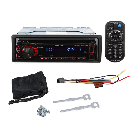
Component Illustrations
Visual representation of various unit components.
Specifications for Kenwood CD Receivers
FM/AM Tuner Specifications
Details frequency ranges, sensitivity, and response for FM/AM tuners.
CD Player Specifications
Details laser diode, digital filter, D/A converter, and playback specs.
Audio Section Specifications
Details output power, impedance, and tone control specs.
Model-Specific Specifications
FM/AM/LW Tuner Specifications
Details tuner specs for E&M destination models.
CD Player & USB Specifications
Details CD player and USB interface specs for E&M models.
Audio & General Specifications
Details audio output and general unit specifications.
Specifications for Model M
FM/AM Tuner and CD Player Specs
Details tuner and CD player performance for Model M.
Audio, USB, and General Specs
Details audio output, USB, and general unit specs for Model M.
Safety Precautions and Warnings
General Safety Precautions
Guidelines for safe operation, maintenance, and replacement parts.
Warning and Cautionary Notes
Important warnings and cautions regarding safety and product integrity.
Critical Safety Components
Identification and replacement guidance for safety-critical parts.
Handling Sensitive Components
Preventing Electrostatic Discharge (ESD)
Methods to prevent damage to laser diodes from static electricity.
Traverse Unit Handling
Precautions for handling the optical pickup traverse unit.
Traverse Unit Decomposition Procedures
Specific steps for disassembling and reassembling the traverse unit.
Laser Product Safety Information
Class 1 Laser Product Warnings
Safety warnings and precautions for Class 1 laser products.
Service Instruction Disclaimer
States that specific service instructions are not described.
Disassembly Procedures
Removing the Bottom Chassis
Step-by-step guide to detach the bottom chassis.
Removing the Front Chassis
Step-by-step guide to detach the front chassis.
Removing the Electric Unit
Steps to remove the main electric unit and its connectors.
Removing the CD Mechanism
Steps to remove the CD mechanism assembly.
Removing the Switch Unit
Steps to remove the switch unit and its cover.
CD Mechanism Assembly Disassembly
Removing the Mecha Control Board
Steps to remove the CD mechanism control board.
Removing the Traverse Mechanism
Steps to remove the traverse mechanism assembly.
Removing the Pickup
Steps to remove the pickup assembly.
Spindle Motor Removal
Removing the Spindle Motor
Detailed steps for detaching the spindle motor.
Loading Motor Removal
Removing the Loading Motor
Detailed steps for detaching the loading motor.
Adjustment and Test Modes
Test Mode Entry and Release
Procedures for entering and exiting various test modes.
Production Test Mode Details
Specific functions and behaviors of the Production Test Mode.
Test Mode Operations
STANDBY Test Mode Specification
Details on operations and display content in STANDBY Test Mode.
Tuner Test and Adjustment Modes
Tuner Test Mode Specifications
Display content and details for various tuner test statuses.
TUNER Setting Adjustment Mode
Procedures for TUNER setting adjustment and AUTO adjustment.
Test Mode Status and Operations
CD Test Mode Specification
Details for CD Test Mode, including playback operations.
CDDA Playback Operations
Specific operations and information displays during CDDA playback.
Service Test Mode Procedures
Service Test Mode Operations
Details on common operation modes for STANDBY sources.
Error Information Modes
CD Error Information Display
Display modes for CD errors, logs, and counts.
DC Error Information Mode
Mode for detecting and displaying DC errors.
Firmware Update Mode
FW Update Special Mode Operations
Flowchart and operations for firmware update mode.
Model-Specific Configuration
FM/AM Channel Space Switching
Procedure for switching FM/AM channel spacing for KDC-U3553.
Troubleshooting Section Disclaimer
States that troubleshooting is not described in this manual.
Parts List Overview
Supported CD Receiver Models
Lists the models covered in the parts list.
Exploded View of Unit Components
Unit Component Identification
Diagram showing exploded view of unit parts with reference numbers.
Unit Parts List
Exploded View Unit Parts
Detailed list of parts for the unit's exploded view.
Unit Parts List Continuation
Instruction Book and Carton Parts
List of instruction books and inner carton parts.
Exploded View of CD Mechanism
CD Mechanism Component Identification
Diagram showing exploded view of CD mechanism parts.
CD Mechanism and Switch Unit Parts
CD Mechanism Parts List
Detailed list of parts for the CD mechanism.
Switch Unit Parts List
Detailed list of parts for the switch unit.
Electronic Component Parts List
LED and Capacitor Parts
List of LED and capacitor components.
Resistor Component Parts List
Resistor Parts Listing
Detailed list of resistor components.
Miscellaneous Component Parts
Resistor, Coil, and Connector Parts
List of various resistors, coils, and connectors.
Capacitor Component Parts List
Capacitor Parts Listing
Detailed list of capacitor components.
Capacitor Parts List Continuation
Capacitor Components List
Further listing of capacitor components.
Component Parts List - Capacitors and Resistors
Capacitor and Resistor Listings
Lists of various capacitor and resistor components.
Resistor Parts List - Section 1
Resistor Components List
Detailed list of resistor components.
Resistor Parts List - Section 2
Resistor Components List
Detailed list of resistor components.
Resistor Parts List - Section 3
Resistor Components List
Detailed list of resistor components.
Resistor Parts List - Section 4
Resistor Components List
Detailed list of resistor components.
Resistor and Coil Parts List
Resistor and Coil Listings
Lists of various resistors and coils.
Schematic Diagrams Overview
CD Receiver Models
Lists the CD receiver models for which schematic diagrams are provided.
System Block Diagram
CD Player Unit Connections
Shows connections for the CD Player Unit.
Electric Unit Connections
Shows connections for the Electric Unit.
Switch Unit Connections
Shows connections for the Switch Unit.
Electric Unit-1 Schematic
Electric Unit-1 Connections
Diagram detailing connections within Electric Unit-1.
Electric Unit-2 Schematic
Electric Unit-2 Connections
Diagram detailing connections within Electric Unit-2.
Switch Unit Schematic
Switch Unit Components and Connections
Diagram of Switch Unit components and their interconnections.
CD Player Unit-1 Schematic
CD Player Unit-1 Circuit Details
Diagram showing the circuitry of CD Player Unit-1.
Electric Unit PCB Layout (GEB10312-001A)
Electric Unit Component Placement
Shows the physical layout of components on the Electric Unit PCB.
Electric Unit PCB Layout - Top View
Electric Unit Component Placement Top View
Top view showing component placement on the Electric Unit PCB.
Switch Unit PCB Layout (GEB10313-001A)
Switch Unit Component Placement
Shows the physical layout of components on the Switch Unit PCB.
Switch Unit PCB Layout - Top View
Switch Unit Component Placement Top View
Top view showing component placement on the Switch Unit PCB.
CD Player Unit-1 PCB Layout (LVB11003-003A)
CD Player Unit-1 Component Placement
Shows the physical layout of components on the CD Player Unit-1 PCB.
CD Player Unit-2 PCB Layout (LVB11003-003A)
CD Player Unit-2 Component Placement
Shows the physical layout of components on the CD Player Unit-2 PCB.
Need help?
Do you have a question about the KDC-MP2052U and is the answer not in the manual?
Questions and answers