Table of Contents
Advertisement
SERVICE MANUAL
Ver. 1.1 2008.08
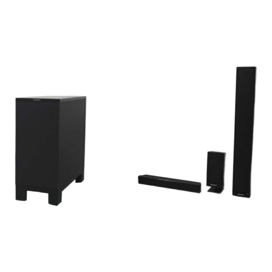
Photo: SA-WSF500
• SA-WFS200 is the active subwoofer in DAV-F200.
• SA-WFS500 is the active subwoofer in DAV-F500.
• SS-CTF500 is the center speaker in DAV-F500.
• SS-TSF200 is the front speaker in DAV-F200.
• SS-TSF500 is the front and Surround speaker in DAV-F500.
• SS-F500 is composed of four SS-TSF500, one SS-CTF500, four Speaker stands and Wall mounting brackets. (for DAV-F500)
Note:
• When SA-WSF200 is checked, it is necessary to connect it with HCD-F200.
• When SA-WSF500 is checked, it is necessary to connect it with HCD-F500.
Speakers
Front speaker (SS-TSF200)
Speaker system
2-Way 2-Driver speaker
system Bass reflex,
Magnetically Shielded
Speaker unit
Woofer: 65 mm cone type
Tweeter: 40 mm cone type
Rated impedance
3 ohms
Dimensions (approx.)
95 mm × 185 mm × 80 mm
(w/h/d)
95 mm × 215 mm × 105
mm (w/h/d) with stand
Mass (approx.)
0.85 kg
0.9 kg with stand
Subwoofer (SA-WSF200)
Amplifier Section
Power output (rated)
108 W + 108 W (at 3 ohms,
1 kHz, 1% THD)
RMS output power (reference)
FL/FR/C*: 141 W
(per channel at 3 ohms,
1 kHz, 10% THD)
Subwoofer*: 141 W (at 3
ohms, 80 Hz, 10% THD)
* Depending on the decoding mode settings and the
source, there may be no sound output.
Sony Corporation
9-889-149-02
2008H05-1
Audio&Video Business Group
©
2008.08
Published by Sony Techno Create Corporation
SS-CTF500/F500/TSF200/TSF500
Photo: SS-CTF500
Photo: SS-TSF200
SPECIFICATIONS
Power requirements:
Thai model:
220 V AC, 50/60 Hz
Other models:
220 V – 240 V AC, 50/60 Hz
Power consumption
On: 105 W
Standby: 0.3 W (at the
Power Saving mode)
Speaker system
Subwoofer Bass reflex
Speaker unit
160 mm cone type
Rated impedance
3 ohms
Dimensions (approx.)
205 mm × 460 mm × 475
mm (w/h/d)
Mass (approx.)
13 kg
Speakers
Front and Surround speaker (SS-TSF500)
Speaker system
2-Way 3-Driver speaker
system Bass reflex,
Magnetically Shielded
Speaker unit
Woofer: 65 mm cone type
× 2
Tweeter: 50 mm cone type
Rated impedance
3 ohms
Dimensions (approx.)
95 mm × 635 mm × 80 mm
(w/h/d)
305 mm × 1,205 mm × 305
mm (w/h/d) with stand
Mass (approx.)
1.8 kg
5.3 kg with stand
SA-WSF200/WSF500/
Canadian Model
Australian Model
Russian Model
SA-WSF500/SS-CTF500/F500/TSF500
Singapore Model
Photo: SS-TSF500
SS-CTF500/F500/TSF200/TSF500
Center speaker (SS-CTF500)
Speaker system
Speaker unit
Rated impedance
Dimensions (approx.)
Mass (approx.)
ACTIVE SUBWOOFER
SPEAKER SYSTEM
E Model
AEP Model
UK Model
SA-WSF200/SS-TSF200
Thai Model
SA-WSF200/WSF500/
Full range, Magnetically
Shielded
30 mm × 50 mm cone type
3 ohms
381 mm × 48 mm × 62 mm
(w/h/d)
0.5 kg
– Continued on next page –
SA-WSF200/WSF500
Advertisement
Table of Contents

Related Manuals for Sony SS-TSF500


Summarization of Contents
SECTION 1 SERVICING NOTES
UNLEADED SOLDER
Details on using unleaded solder and its characteristics.
MODEL IDENTIFICATION
Identifies different models and their corresponding part numbers.
PRE-REPAIR PREPARATION
Steps to prepare before starting repair for SA-WSF200 and SA-WSF500.
SECTION 2 GENERAL
SA-WSF200 Subwoofer Overview
Identifies rear and bottom view connections and features of SA-WSF200.
SA-WSF500 Subwoofer Overview
Identifies rear and bottom view connections and features of SA-WSF500.
SECTION 3 DISASSEMBLY
DISASSEMBLY FLOW (SA-WSF200/WSF500)
Outlines the step-by-step procedure for disassembling the set.
BOARD REMOVAL
Instructions for removing the AMP-DSP and POWER boards.
SECTION 4 DIAGRAMS
BLOCK DIAGRAMS
Illustrates block diagrams for DSP, AMP, and Power Supply sections.
PRINTED WIRING BOARDS (PWBs)
Component and conductor layout views for AMP-DSP, SPEAKER, POWER, and REG boards.
SCHEMATIC DIAGRAMS
Detailed circuit schematics for AMP-DSP, SPEAKER, POWER, and REG boards.
WAVEFORMS
Displays various waveforms from the AMP-DSP board for analysis.
IC BLOCK DIAGRAMS
Block diagrams for key ICs on the AMP-DSP board.
SPECIFICATIONS
TUNER SECTION
Details FM tuner specifications including tuning range and antenna terminals.
DVD SYSTEM
Information on the DVD system, laser type, and emission duration.
USB SECTION
Specifications for USB port, supported bit rates, and sampling frequencies.
VIDEO SECTION OUTPUTS
Details video outputs like VIDEO, COMPONENT, and HDMI.
SECTION 1 SERVICING NOTES
MODEL IDENTIFICATION
Identifies different HCD models and their corresponding part numbers.
PRE-REPAIR PREPARATION
Steps to prepare before starting repair for HCD-F200 and HCD-F500.
SECTION 2 GENERAL
Control unit HCD-F200 Overview
Identifies front, top, side views and panel controls of the HCD-F200.
Control unit HCD-F500 Overview
Identifies front, top, side views and panel controls of the HCD-F500.
SECTION 3 DISASSEMBLY
DISASSEMBLY FLOW
Outlines the step-by-step procedure for disassembling the HCD unit.
OPTICAL PICK-UP BLOCK
Procedure for removing the optical pick-up block.
MAIN BOARD
Procedure for removing the main board.
DVD MECHANISM BLOCK
Procedure for removing the DVD mechanism block.
SECTION 4 TEST MODE
TEST MODES OTHER THAN THE TEST MENU
Executable test modes without entering the main test menu.
DVD Service Mode General Description
General description of the DVD service mode for diagnosis and adjustment.
Executing IOP Measurement
Standard procedures for executing IOP measurement.
SECTION 5 ELECTRICAL ADJUSTMENTS
EXECUTING IOP MEASUREMENT
Procedure for executing IOP measurement as shown in the diagrams.
FM TUNE LEVEL CHECK
Procedure for checking FM tune level using a signal generator.
SECTION 6 DIAGRAMS
Block Diagram - DVD SERVO Section
Block diagram illustrating the DVD servo system.
Block Diagram - MAIN Section
Block diagram of the main section including tuner, DMPORT, and audio paths.
Printed Wiring Boards - DMB-FIT Section (1/2)
Component layout view of the DMB-FIT board, part 1.
Schematic Diagram - MAIN Board (1/3)
Schematic diagram of the MAIN board, part 1.
SECTION 7 EXPLODED VIEWS
REAR COVER SECTION
Exploded view of the rear cover components.
FRONT PANEL SECTION
Exploded view of the front panel assembly components.
MAIN SECTION
Exploded view of the main chassis and internal board components.
SECTION 8 ELECTRICAL PARTS LIST
DMB-FIT
List of electrical parts for the DMB-FIT board.
KEY-L BOARD
List of electrical parts for the KEY-L board.
KEY-R BOARD
List of electrical parts for the KEY-R board.
Need help?
Do you have a question about the SS-TSF500 and is the answer not in the manual?
Questions and answers