Table of Contents
Advertisement
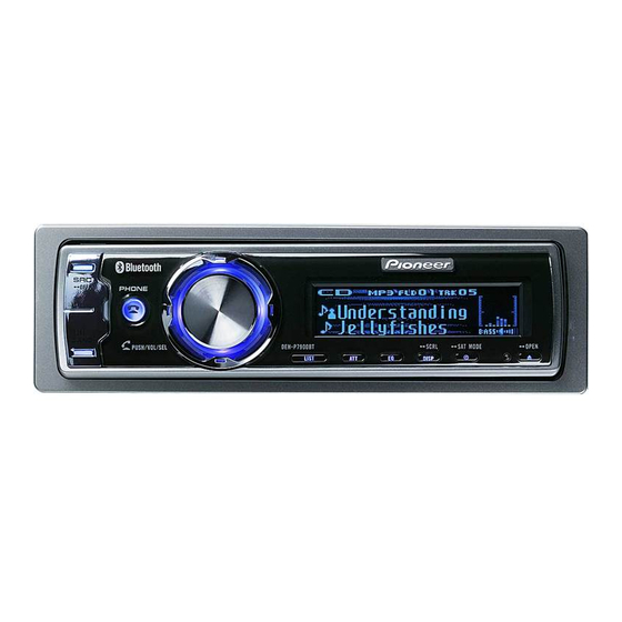
CD RECEIVER
DEH-P790BT
DEH-P7900BT
DEH-P8950BT
This service manual should be used together with the following manual(s):
Model No.
Order No.
CX-3195
CRT3815
For details, refer to "Important Check Points for Good Servicing".
PIONEER CORPORATION
PIONEER ELECTRONICS (USA) INC. P.O. Box 1760, Long Beach, CA 90801-1760, U.S.A.
PIONEER EUROPE NV Haven 1087, Keetberglaan 1, 9120 Melsele, Belgium
PIONEER ELECTRONICS ASIACENTRE PTE. LTD. 253 Alexandra Road, #04-01, Singapore 159936
PIONEER CORPORATION 2007
Mech.Module
S10.5COMP2
CD Mech. Module : Circuit Descriptions, Mech. Descriptions, Disassembly
4-1, Meguro 1-chome, Meguro-ku, Tokyo 153-8654, Japan
DEH-P790BT/XN/UC
/XN/UC
/XN/ES
Remarks
ORDER NO.
CRT3903
/XN/UC
K-ZZA. MAR. 2007 Printed in Japan
Advertisement
Table of Contents

Related Manuals for Pioneer DEH-P8950BT


Summarization of Contents
Important Check Points for Good Servicing
Product safety
Ensure product safety and maintain a safe servicing environment.
Adjustments
Perform optimum adjustments for product performance.
Lubricants, Glues, and Replacement parts
Use specified lubricants and adhesives for repairs.
Cleaning
Clean parts to restore performance.
SPECIFICATIONS
General Specs
General specifications including power, dimensions, and weight.
Audio Specs
Audio output power, impedance, and equalizer specifications.
Component Specs
Specifications for CD player, tuners, and Bluetooth.
EXPLODED VIEWS AND PARTS LIST
PACKING
Exploded view and parts list for the packing of DEH-P790BT/XN/UC model.
EXTERIOR PARTS
Diagram and list of external parts for the unit (Parts 1 & 2).
CD MECHANISM MODULE
Exploded view and parts list for the CD mechanism module.
BLOCK DIAGRAM AND SCHEMATIC DIAGRAM
BLOCK DIAGRAM
High-level functional overview of the unit's architecture.
UNIT BLOCK DIAGRAMS
Block diagrams for Keyboard, Bluetooth, Antenna, Tuner Amp, and CD Mechanism units.
PCB CONNECTION DIAGRAM
TUNER AMP UNIT PCB
PCB connection diagram for the tuner amplifier section.
KEYBOARD UNIT PCB
PCB connection diagram for the keyboard control section.
CD CORE UNIT PCB
PCB connection diagram for the CD core unit.
BLUETOOTH UNIT PCB
PCB connection diagram for the Bluetooth unit.
ADJUSTMENT
CD ADJUSTMENT
Procedures for adjusting CD playback functions.
CHECKING THE GRATING
Procedure to check pickup unit grating after replacement.
ERROR MODE
List and explanation of error codes and their causes.
TEST MODES
Test modes for iPod, USB, and Bluetooth functionalities.
GENERAL INFORMATION
DIAGNOSIS & DISASSEMBLY
Diagnostic information and step-by-step disassembly instructions.
CONNECTOR & IC FUNCTION DESCRIPTIONS
Descriptions for connector pins and integrated circuits (ICs).
OPERATIONAL FLOW CHART
Flow chart illustrating operational sequences and logic.
OPERATIONS
Head unit Controls
Description of controls and functions on the main unit.
Remote control Operations
Description of controls and functions for the remote control.
Bluetooth Test Mode (BT-compliant mobile phone)
Specifications for BT Built-in mobile phone
Specifies requirements for BT-compliant mobile phones.
Need help?
Do you have a question about the DEH-P8950BT and is the answer not in the manual?
Questions and answers