Table of Contents
Advertisement
Register at www.Toro.com.
Original Instructions (EN)
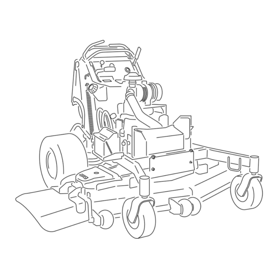
GrandStand
With 48in, 52in, or 60in TURBO FORCE
Cutting Unit
Model No. 74583—Serial No. 315000001 and Up
Model No. 74588—Serial No. 315000001 and Up
Model No. 74589—Serial No. 315000001 and Up
Model No. 79589—Serial No. 315000001 and Up
Form No. 3390-206 Rev A
®
Mower
®
g017600
*3390-206* A
Advertisement
Table of Contents

Related Manuals for Toro GrandStand 74588


Summary of Contents for Toro GrandStand 74588
-
Page 1: Cutting Unit
® Cutting Unit Model No. 74583—Serial No. 315000001 and Up Model No. 74588—Serial No. 315000001 and Up Model No. 74589—Serial No. 315000001 and Up Model No. 79589—Serial No. 315000001 and Up g017600 *3390-206* A Register at www.Toro.com. Original Instructions (EN) - Page 2 You may contact Toro directly at www.Toro.com for product WARNING and accessory information, help finding a dealer, or to register your product. CALIFORNIA Proposition 65 Warning Whenever you need service, genuine Toro parts, or additional This product contains a chemical or chemicals...
-
Page 3: Table Of Contents
Safety ................4 Adjusting the Tracking ...........41 Safe Operating Practices........... 4 Checking the Tire Pressure ........42 Toro Mower Safety ..........6 Adjusting the Caster-Pivot Bearing......42 Slope Indicator ............7 Servicing the Caster Wheels and Bearings....43 Safety and Instructional Decals ......... 8 Servicing the Clutch..........43... -
Page 4: Safety
Use extra care when handling fuels. They are flammable Manual. Modifications to this machine should only be and vapors are explosive. made by either the manufacturer or an Authorized Toro Dealer. – Use only an approved container. – Do not remove the fuel cap or add fuel with the This product is capable of amputating hands and feet. -
Page 5: Maintenance And Storage
• • Do not change the engine governor setting or overspeed If fuel is spilled on clothing, change your clothing the engine. immediately. • Stop on level ground, disengage drives, engage the • Do not overfill fuel tank. Replace fuel cap and tighten parking brake (if provided), shut off the engine before securely. -
Page 6: Toro Mower Safety
Toro Mower Safety Slope Operation All slopes and ramps require extra caution. If you feel uneasy The following list contains safety information specific to Toro on a slope, do not mow it. products and other safety information you must know. -
Page 7: Slope Indicator
Slope Indicator G011841 Figure 3 This page may be copied for personal use. 1. The maximum slope you can safely operate the machine on is 20 degrees. Use the slope chart to determine the degree of slope of hills before operating. Do not operate this machine on a slope greater than 20 degrees. Fold along the appropriate line to match the recommended slope. -
Page 8: Safety And Instructional Decals
Safety and Instructional Decals Safety decals and instructions are easily visible to the operator and are located near any area of potential danger. Replace any decal that is damaged or lost. Manufacturer's Mark 1. Indicates the blade is identified as a part from the original 93-7818 machine manufacturer. - Page 9 116-8772 1. Accessory, 15A 3. Charge, 25A 2. PTO, 10A 4. Main, 30A 120-6412 1. Belt tension adjustment; read the Operator's Manual for more information. 116-8775 1. Read the Operator’s 2. Fill to bottom of filler neck; Manual. warning—Do not overfill the tank.
- Page 10 121-6049 1. Thrown object 3. Cutting/dismemberment hazard—keep bystanders hazard of hand or foot, away from the machine. mower blade—keep hands away from moving parts. 2. Thrown object hazard, mower—do not operate the mower with guards or shields removed. 131-1180 1. Read the Operator's Manual. (A) Short, light grass; dry conditions;...
- Page 11 119-8727 1. Traction control 3. Slow 5. Reverse 7. Operator presence switch 2. Fast 4. Neutral 6. Power Take-off (PTO)—disengage...
-
Page 12: Product Overview
Controls Product Overview Become familiar with all the controls (Figure 5) before you start the engine and operate the machine. g020878 g017733 Figure 5 Figure 4 1. Parking-brake lever 8. Height-of-cut pin 1. Side-discharge chute 7. Control levers 2. Malfunction-indicator light 9. -
Page 13: Throttle Control
3. Hour meter 1. Safety-interlock symbols its capabilities. Contact your Authorized Service Dealer or 2. Battery light Distributor or go to www.Toro.com for a list of all approved attachments and accessories. Throttle Control The throttle control is variable between Fast and Slow. -
Page 14: Specifications
Specifications Operation Note: Specifications and design are subject to change Note: Determine the left and right sides of the machine without notice. from the normal operating position. 48-inch Mowers Adding Fuel Width with deflector down 161.3 cm (63.5 inches) Width with deflector raised 125.7 cm (49.5 inches) •... -
Page 15: Checking The Engine-Oil Level
of varnish deposits in the fuel system, use fuel stabilizer DANGER at all times. In certain conditions during fueling, static electricity can be released causing a spark which Filling the Fuel Tank can ignite the gasoline vapors. A fire or explosion 1. -
Page 16: Operating The Parking Brake
Operating the Parking Brake Always set the parking brake when you stop the machine or leave it unattended. Before each use, check the parking brake for proper operation. If the parking brake does not hold securely, adjust it; refer to Servicing the Brake (page 47). -
Page 17: Operating The Ignition Switch
Operating the Ignition Switch Using the Fuel Shut-off Valve 1. Turn the ignition key to the Start position (Figure 12). Close the fuel shut-off valve for transport, maintenance, and When the engines starts, release the key. storage (Figure 13). Important: Do not engage the starter for more Ensure that the fuel shut-off valve is open when starting the than 5 seconds at a time. -
Page 18: Stopping The Engine
Stopping the Engine CAUTION Children or bystanders may be injured if they move or attempt to operate the tractor while it is unattended. Always remove the ignition key and set the parking brake when leaving the machine unattended, even if just for a few minutes. Let the engine idle at slow throttle (turtle) for 60 seconds before turning the ignition switch off. -
Page 19: The Safety-Interlock System
The Safety-Interlock System Note: The blades should not rotate. 4. Move the motion-control levers forward. CAUTION Note: The engine should stop running. If safety-interlock switches are disconnected or 5. Start the engine and release the parking brake. damaged the machine could operate unexpectedly causing personal injury. -
Page 20: Operating The Platform
Operating the Platform The machine can be used with the platform in the up or down position. It is the operator's preference on which position to use. Operating the Machine with the Platform Up Operating the machine with the platform up is recommended for the following: •... - Page 21 Driving Forward 1. Release the parking brake; refer to Releasing the Parking Brake (page 16). 2. Move the right side motion-control lever to the center, unlocked position. Figure 20 Driving Backward G015234 1. Move the right side motion-control lever to the center, Figure 19 unlocked position.
-
Page 22: Stopping The Machine
Stopping the Machine Pushing the Machine by Hand The bypass valves allow the machine to be pushed by hand To stop the machine, move the motion-control levers to without the engine running. neutral, move the right side motion-control lever into the neutral-lock position, disengage the power-take off (PTO), Important: Always push the machine by hand. -
Page 23: Loading The Machine
3. If applicable, connect the trailer brakes. WARNING 4. Load the machine onto the trailer or truck. Loading a unit onto a trailer or truck increases the possibility of backward tip-over, and could cause 5. Stop the engine, remove the key, set the brake, and serious injury or death. -
Page 24: Adjusting The Height-Of-Cut
Adjusting the Anti-Scalp DANGER Rollers (for 60-inch models Without the grass deflector, discharge cover, or complete grass catcher assembly mounted in only) place, you and others are exposed to blade contact and thrown debris. Contact with rotating mower Whenever you change the height-of-cut, it is recommended blade(s) and thrown debris will cause injury or to adjust the height of the anti-scalp rollers. -
Page 25: Positioning The Flow Baffle
Position B Use this position when bagging (Figure 30). g012676 Figure 28 1. Slot 2. Nut G012678 Figure 30 Positioning the Flow Baffle The following figures are only for recommended use. Adjustments will vary by grass type, moisture content, and Position C the height of the grass. -
Page 26: Using The Mid-Size Weight
Using the Mid-Size Weight • Weights are installed to improve handling, balance, and improve performance. Weights can be added or removed to create optimized performance under different mowing conditions and for operator preference. • It is recommended that weights be added or removed one at a time until the desired handing and balance is achieved. -
Page 27: Maintenance
• Check the inner-air filter. • Adjust the caster-pivot bearing. • Check the wheel-hub nuts. Every 500 hours • Change the hydraulic filter and hydraulic oil when using Toro® HYPR-OIL™ 500 hydraulic oil. • Replace the inner-air filter. Every 600 hours •... -
Page 28: Premaintenance Procedures
CAUTION If you leave the key in the ignition switch, someone could accidently start the engine and seriously injure you or other bystanders. Remove the key from the ignition and disconnect the spark-plug wires from the spark plugs before you do any maintenance. -
Page 29: Releasing The Cushion For Rear Access
Figure 34 g019209 1. Remove battery 2. Front end of the mower Figure 35 1. Plastic bushing with the 3. Hairpin-cotter pin large washer Releasing the Cushion for 2. Cushion bracket with the Rear Access key hole You can release the cushion for rear access to the machine for maintenance or adjustment. -
Page 30: Lubrication
Lubrication Grease with No. 2 general purpose lithium base or molybdenum base grease. Lubricating the Machine Service Interval: Every 50 hours—Grease the lift linkage (more often in dirty or dusty conditions). Every 50 hours—Grease the mower deck spindles (more often in dirty or dusty conditions). g017739 Every 800 hours/Yearly (whichever comes Figure 38... -
Page 31: Lubricate Caster-Wheel Hubs
Lubricate Caster-Wheel Hubs 13. Torque the nut to 8 to 9 N-m (71 to 80 in-lb), loosen, then torque it to 2 to 3 N-m (20 to 25 in-lb). Service Interval: Yearly Note: Make sure axle does not extend beyond either 1. -
Page 32: Engine Maintenance
Engine Maintenance 7. Inspect the primary filter for damage by looking into the filter while shining a bright light on the outside of the filter. Servicing the Air Cleaner Note: Holes in the filter will appear as bright spots. Service Interval: Every 150 hours Note: If the filter is damaged, discard it. -
Page 33: Servicing The Engine Oil
Servicing the Engine Oil Oil Type: Detergent oil (API service class SJ or higher) Oil Capacity: with a filter change, 1.9 L (61 oz); with no filter change, 1.6 L (54 oz) Viscosity: See the table below. SAE 30 g017552 Figure 41 Checking the Engine-Oil Level Service Interval: Before each use or daily... -
Page 34: Changing The Engine Oil
Changing the Engine Oil 4. Slowly pour approximately 80% of the specified oil into the filler tube and slowly add the additional oil to Service Interval: Every 100 hours (more often in dirty or bring it to the Full mark (Figure 44). -
Page 35: Servicing The Spark Plug
Changing the Engine-Oil Filter Use a spark plug wrench for removing and installing the spark plug(s) and a gapping tool/feeler gauge to check and adjust Service Interval: Every 200 hours the air gap. Install a new spark plug(s) if necessary. Note: Change the engine-oil filter more frequently when Type for all Engines: Kohler 25 132 14-c Champion operating conditions are extremely dusty or sandy. -
Page 36: Checking The Spark Arrester (If Equipped)
Installing the Spark Plug Fuel System Tighten the spark plug(s) to 22 N-m (16 ft-lb). Maintenance Draining the Fuel Tank Note: There is no other recommended way to drain fuel from the tank, other than using a syphon pump. A syphon pump can be purchased at a hardware store. -
Page 37: Servicing The Fuel Filter
Servicing the Fuel Filter Servicing the Electronic Fuel-Injection System Replacing the Fuel Filter This machine contains an electronic fuel-injection system. It Service Interval: Every 800 hours/Yearly (whichever comes controls the fuel flow under different operating conditions. first) The electronic-control unit (ECU) continuously monitors the Do not install a dirty filter if it is removed from the fuel line. -
Page 38: Electrical System Maintenance
Electrical System WARNING Maintenance Incorrect battery-cable routing could damage the machine and cables causing sparks. Sparks can cause the battery gasses to explode, resulting in Servicing the Battery personal injury. • Always disconnect the negative (black) battery Service Interval: Every 100 hours cable before disconnecting the positive (red) Always keep the battery clean and fully charged. -
Page 39: Servicing The Fuses
Installing the Battery 1. Place the battery onto the machine (Figure 51). 2. Secure the battery with the hold down plate, j-bolts, and locknuts. 3. Install the positive (red) battery cable to positive (+) battery terminal with a nut, a washer, and a bolt (Figure 51). -
Page 40: Jump Starting The Machine
Jump Starting the Machine same rated system voltage. These instructions are for negative ground systems only. 1. Check and clean corrosion from the battery terminals 4. Connect the positive (+) cable to the positive (+) before jump starting the machine. Ensure that the terminal of the discharged battery that is wired to the connections are tight. -
Page 41: Drive System Maintenance
Drive System Maintenance Adjusting the Tracking Note: Determine the left and right sides of the machine from the normal operating position. 1. Push both control levers forward the same distance. 2. Check if the machine pulls to one side. Note: If it does, stop the machine and set the parking brake. -
Page 42: Checking The Tire Pressure
Checking the Tire Pressure Service Interval: Every 50 hours/Monthly (whichever comes first) Maintain the air pressure in the rear tires at 83 to 97 kPa (12 to 14 psi). Important: Uneven tire pressure can cause an uneven cut. Note: The front tires are semi-pneumatic tires and do not require air-pressure maintenance. -
Page 43: Servicing The Caster Wheels And Bearings
2. Remove one bushing, then pull the spanner bushing and roller bearing out of the wheel hub (Figure 61). 3. Remove the other bushing from the wheel hub, and clean any grease and dirt from the wheel hub (Figure 61). 4. - Page 44 Figure 64 Figure 62 1. Brake-mounting bolt 1. Armature 5. Brake spacer 2. Field shell 6. Re-gap shim B. Using needle nose pliers, or by hand, take hold of the tab and remove the shim (Do not discard the 3. Rotor 7.
-
Page 45: Checking The Wheel-Lug Nuts
Cooling System Maintenance Cleaning the Air-Intake Screen Service Interval: Before each use or daily Before each use, remove any buildup of grass, dirt, or other debris from the cylinder and cylinder head cooling Figure 67 fins, air intake screen on the flywheel end, and the carburetor-governor levers and linkage. -
Page 46: Servicing The Engine-Oil Cooler
Servicing the Engine-Oil Servicing the Hydraulic-Oil Cooler Cooler Service Interval: Every 200 hours Service Interval: Every 100 hours—Service the hydraulic-oil cooler in dirty conditions (if equipped). 1. Keep the oil cooler free of debris by cleaning the fins with a brush. 1. -
Page 47: Brake Maintenance
Brake Maintenance Servicing the Brake Before each use, check the brakes on a level surface and slope. Always set the parking brake when you stop the machine or leave it unattended. Important: If the parking brake does not hold securely, an adjustment is required. -
Page 48: Adjusting The Brakes
Adjusting the Brakes If the parking brake does not hold securely, an adjustment is required. 1. Check the brake before you adjust it; refer to Checking the Parking Brake (page 47). 2. Park the machine on a level surface, disengage the PTO, and set the parking brake. -
Page 49: Belt Maintenance
Belt Maintenance Replacing the Mower-Deck Belt Service Interval: Every 100 hours—Check the mower-deck belt. Squeaking when the belt is rotating, the blade is slipping when cutting grass, frayed belt edges, burn marks, and cracks are signs of a worn deck belt. Replace the deck belt if any of these conditions are evident. -
Page 50: Replacing The Pump-Drive Belt
g017890 Figure 75 1. 16.5 cm (6.5 inches) from 4. Ratchet hook to hook 2. Spring 5. Square hole for ratchet G015402 3. Spring-loaded idler 6. Nut Figure 76 1. Hydraulic pumps 4. Clutch retainer Replacing the Pump-drive Belt 2. Idler pulley 5. -
Page 51: Controls System Maintenance
Controls System Maintenance Adjusting the Motion-Control-Handle Positions Adjusting the Right Side Motion-Control Lever If the motion-control levers do not align horizontally, adjust the right side motion-control lever. Note: Adjust the horizontal alignment before the front to back alignment. 1. Disengage the PTO, move the right side motion-control lever to the neutral position, and set the parking brake. - Page 52 Adjusting the Neutral Position for the Motion-Control Levers Important: Ensure the tracking of the mower is correct after adjusting the motion-control levers. Adjusting the tracking and aligning the motion-control levers front to back is the same procedure (Figure 79). Note: Adjust the horizontal alignment before the front to back alignment.
-
Page 53: Hydraulic System Maintenance
(Figure 81). System 9. Install the cap on the filler neck. ® ™ Hydraulic Oil Type: Toro HYPR-OIL 500 hydraulic oil WARNING ® or Mobil 1 15W-50 synthetic motor oil. Hydraulic fluid escaping under pressure can Hydraulic System Oil Capacity: 2 L (67 oz) penetrate skin and cause injury. - Page 54 Replacing the Hydraulic Filter 5. Loosen the hose clamp and move it down the hose. 6. Remove the front hydraulic hose, and allow the fluid to Service Interval: After the first 8 hours run out of the tank. WARNING Hot hydraulic fluid can cause severe burns. Allow the hydraulic fluid to cool before performing any maintenance to the hydraulic system.
-
Page 55: Bleeding The Hydraulic System
Checking the Hydraulic Lines Service Interval: Every 100 hours Check hydraulic hoses and hoses for leaks, loose fittings, kinked hoses, loose mounting supports, wear, general weathering, and chemical deterioration. Make any necessary repairs before operating. Note: Keep areas around the hydraulic system clean from grass and debris buildup. -
Page 56: Mower Deck Maintenance
Mower Deck Checking for Bent Blades 1. Disengage the PTO, move the motion-control levers to Maintenance the neutral-locked position, and set the parking brake. 2. Stop the engine, remove the key, and wait for all moving Servicing the Cutting Blades parts to stop before leaving the operating position. -
Page 57: Removing The Blades
To ensure optimum performance and continued safety conformance of the machine, use genuine Toro replacement blades. Replacement blades made by other manufacturers may result in nonconformance with safety standards. -
Page 58: Correcting The Mower Quality-Of-Cut
Correcting the Mower Changing the Mower Deck Side-to-Side Height Quality-of-Cut Changing the side-to-side height is done by adjusting the If one deck blade cuts lower than the other, correct it as rear-tire pressure and U-plates on the side of the engine deck. follows: 1. - Page 59 4. For 60-inch mower decks, loosen both the front and rear nuts and lift links on the adjustment rods (Figure 96). Note: The weight of the mower deck must be resting on all 3 of the 2x4 pieces (Figure 95). Note: The back lip of the mower deck is built 6mm (1/4 inch) lower than the front lip of the mower deck.
- Page 60 Figure 97 1. Measure from a level 2. Measure the blade at point surface 5. If it does not measure correctly, locate the height-of-cut rod on the right side of the machine (Figure 98). 6. Adjust the adjustment bolt until the blade tips match 7.6 cm (3 inches) as shown in Figure G015501...
-
Page 61: Adjusting The Deck-Lift Spring
Adjusting the Deck-Lift Spring Replacing the Grass Deflector Note: Adjusting the deck-lift spring will alter how much the WARNING deck will float and how much effort it takes to lift the deck when using the height-of-cut handle. An uncovered discharge opening could allow the lawn mower to throw objects in the operator's or 1. -
Page 62: Cleaning
Cleaning Storage Cleaning and Storage Cleaning under the Mower 1. Disengage the power take off (PTO), set the parking Service Interval: Before each use or daily brake, turn the ignition key to off, and remove the key. Remove the grass buildup under the mower daily. 2. - Page 63 12. Paint all scratched or bare metal surfaces. Paint is available from your Authorized Service Dealer. 13. Store the machine in a clean, dry garage or storage area. Remove the key from the ignition switch and keep it in a memorable place. Cover the machine to protect it and keep it clean.
-
Page 64: Troubleshooting
Troubleshooting Problem Possible Cause Corrective Action The engine will not start, starts hard, or 1. The fuel tank is empty or shut-off valve 1. Fill fuel tank with gasoline and open fails to keep running. closed. valve 2. The spark plug wire is loose or 2. - Page 65 Problem Possible Cause Corrective Action The cutting blades do not rotate. 1. The drive belt is worn, loose or broken. 1. Check the belt tension. 2. The drive belt is off pulley. 2. Install the drive belt and check the adjusting shafts and belt guides for correct position.
-
Page 66: Schematics
Schematics g017891 Hydraulic Schematic (Rev. A) - Page 67 g018109 Electrical Schematic (Rev. A)
- Page 68 Customers who have purchased Toro products outside the United States or Canada should contact their Toro Distributor (Dealer) to obtain guarantee policies for your country, province, or state. If for any reason you are dissatisfied with your Distributor's service or have difficulty obtaining guarantee information, contact the Toro importer. If all other remedies fail, you may contact us at Toro Warranty Company.
Need help?
Do you have a question about the GrandStand 74588 and is the answer not in the manual?
Questions and answers