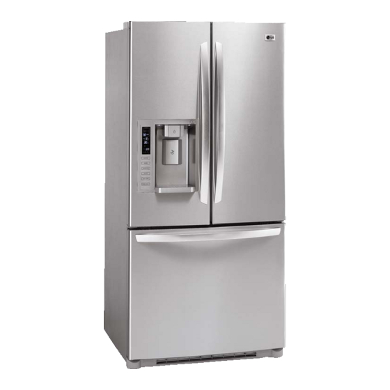
Summarization of Contents
3. DISASSEMBLY PROCEDURES
3-1 REFRIGERATOR DOORS
Procedures for removing and replacing refrigerator doors.
3-2 REFRIGERATOR HANDLES
Procedures for removing refrigerator handles.
3-3 FREEZER HANDLE & DOOR GASKET REMOVAL
Procedures for removing freezer handles and door gaskets.
3-4 DOOR GASKET REPLACEMENT & ALIGNMENT
Steps for replacing the door gasket and adjusting door alignment.
3-5 FAN & MOTOR REPLACEMENT
How to remove and replace the evaporator fan and motor.
3-6 DEFROST CONTROL ASSEMBLY
How to replace the defrost control assembly.
3-7 LAMP & DUCT REPLACEMENT
Procedures for replacing lamps and the multi-duct.
3-8 MAIN & DISPLAY PCB REPLACEMENT
Instructions for replacing Main PCB and Display PCB.
3-9 ICEMAKER & DISPENSER COMPONENTS
Steps for replacing icemaker, ice button, funnel, water button, duct door, ice corner door.
3-10 AUGER MOTOR COVER REPLACEMENT
Procedures for removing and replacing the auger motor cover.
3-11 ICE BIN HANDLING
Steps for removing and inserting the door ice bin.
3-12 PULL OUT DRAWER INSTALLATION
Instructions for installing the pull-out drawer.
3-13 PULL OUT DRAWER REMOVAL
Instructions for removing the pull-out drawer.
3-14 FAN AND FAN MOTOR DISASSEMBLY METHOD
Method for disassembling fan and fan motor.
4. ADJUSTMENT AND COMPONENT ANALYSIS
4-1 COMPRESSOR & PTC-STARTER
Role, composition, usage notes, and circuit diagrams for compressor and PTC starter.
4-2 OLP (OVERLOAD PROTECTOR)
Definition and role of the Overload Protector (OLP).
4-3 PTC COVER REMOVAL
Steps for removing the PTC cover.
6. TROUBLESHOOTING GUIDE
6-1 COMPRESSOR & ELECTRICAL COMPONENTS
Troubleshooting compressor and related electrical components.
6-2 OTHER ELECTRICAL COMPONENTS
Troubleshooting for other electrical components and general issues.
6-3 SERVICE DIAGNOSIS CHART
A chart for diagnosing common refrigerator complaints and remedies.
6-4 REFRIGERATION CYCLE ISSUES
Troubleshooting common refrigeration cycle problems like leaks and clogs.
7. ICEMAKER OPERATION & DIAGNOSIS
7-1 ICEMAKER OPERATION PRINCIPLES
Explains the basic operation and modes of the ice maker.
7-2 ICE MAKER FUNCTIONS & MODES
Details on Icemaking, Harvest, Fill/Park modes, and water supply.
7-3 ICEMAKER TEST & DEFECT DIAGNOSIS
Information on function testing and error codes for the ice maker.
8. MICOM FUNCTION & CIRCUITRY
8-1 USER INTERFACE & MODES
Display functions, temperature toggling, lock, filter status, Ice Plus, dispenser, and door alarms.
8-2 MOTOR & SENSOR CONTROL
Control of fan motors, icing fan, and their sensing methods.
8-3 DEFROSTING & DIAGNOSTICS
Procedures for defrosting and defect diagnosis functions.
8-4 TEST MODES
Procedures and tables for various product test modes.
8-5 PCB & CIRCUIT ANALYSIS
Analysis of power, load, fan, sensor, damper, and dispenser circuits.
8-6 PWB ASSEMBLY & PARTS
Identification and listing of parts for Main PWB and Dispenser Drive PWB.
9. EXPLODED VIEW OF COMPONENTS
9-1 CASE PARTS
Exploded view of the main cabinet and external case components.
9-2 FREEZER PARTS
Exploded view of freezer compartment components.
9-3 REFRIGERATOR PARTS
Exploded view of refrigerator compartment components.
9-4 DOOR PARTS
Exploded view of refrigerator door components.
9-5 DISPENSER PARTS
Exploded view of dispenser assembly components.
9-6 ICE MAKER & ICE BANK PARTS
Exploded view of ice maker and ice bank components.
9-7 VALVE & Water Parts
Exploded view of water valve and related plumbing components.


Need help?
Do you have a question about the LFX23961ST /01 and is the answer not in the manual?
Questions and answers