Table of Contents
Advertisement
Quick Links
Download this manual
See also:
User Manual
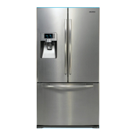
REFRIGERATOR
RF267AB
For the latest parts information, Please access to our service web site
(● North America : http://service.samsungportal.com)
REFRIGERATOR
BASIC : RF267AB
MODEL NAME : RF267ABRS
RF267ABBP
RF267AABWP
RF267ABPN
MODEL CODE : RF267ABRS/XAA
RF267ABBP/XAA
RF267ABWP/XAA
RF267ABPN/XAA
CONTENTS
1. PRECAUTIONS(SAFETY WARNINGS)
2. PRODUCT SPECIFICATIONS
3. DISASSEMBLY AND REASSEMBLY
4. TROUBLESHOOTING
5 . EXPLODED VIEW & PARTS LIST
6. PCB DIAGRAM
· · · · · · · · · · · · · · · · · · · · · · · · · · · · · · · · · · · · · ·
7. WIRING DIAGRAM
· · · · · · · · · · · · · · · · · · · · · · · · · · · · · · · ·
8. SCHEMATIC DIAGRAM
4
· ·
7
· · · · · · · · · · · · · · · ·
20
· · · ·
46
· · · · · · · · · · · · · · · · · · · · · · · · · · · · · ·
83
· · · · · · · ·
103
108
109
· · · · · · · · · · · · · · · · · · · · · · · ·
Advertisement
Table of Contents

Summarization of Contents
PRODUCT SPECIFICATIONS
INTRODUCTION OF MAIN FUNCTION
Overview of key features and characteristics of the refrigerator model.
SPECIFICATIONS
Detailed technical specifications including electrical, performance, and refrigeration system data.
INTERIOR VIEWS
Diagrams illustrating the internal layout and components of the refrigerator and freezer.
MODEL SPECIFICATION
Comparative specifications across different models, including performance metrics.
MODEL SPECIFICATION &SPECIFICATION CHART
Detailed specification chart for the RF267AB model, covering external size and capacity.
DIMENSIONS OF REFRIGERATOR (INCHES)
Visual representation of refrigerator dimensions with key measurements for installation.
OPTIONAL MATERIAL SPECIFICATION
List of optional parts and their specifications, like water filters and lamps.
REFRIGERANT ROUTE IN REFRIGERATION CYCLE
Diagram and description showing the path of the refrigerant in the cooling system.
COOLING AIR CIRCULATION
Diagrams illustrating the airflow within the refrigerator and freezer compartments.
DISASSEMBLY AND REASSEMBLY
PRECAUTION
Essential safety precautions and necessary tools before performing disassembly procedures.
REFRIGERATOR DOOR
Step-by-step guide for removing and installing the refrigerator door.
DOOR HANDLE
Instructions for disassembling and reassembling the freezer door handle.
WATER FILTER (DISASSEMBLY)
Steps for removing the water filter from its housing.
EVAPORATOR IN REFRIGERATOR
Procedure for disassembling the evaporator unit in the refrigerator.
FREEZER DOOR
Steps for disassembling the freezer door.
ICE-MAKER
Guide on how to disassemble the ice maker assembly.
ELECTRIC BOX
Guide on how to access and disassemble the electric control box (PCBs).
TROUBLESHOOTING
FUNCTION FOR FAILURE DIAGNOSIS
Overview of functions for diagnosing refrigerator failures and error codes.
DIAGNOSTIC METHOD ACCORDING TO THE TROUBLE SYMPTOM(FLOW CHART)
Detailed flow charts to diagnose issues based on specific symptoms and error codes.
EXPLODED VIEW & PARTS LIST
FREEZER
Exploded view diagrams and parts list for the freezer section.
REFRIGERATOR
Exploded view diagrams and parts list for the refrigerator section.
CABINET
Exploded view diagrams and parts list for the refrigerator cabinet and housing.
DISASSEMBLY OF FREEZE DOOR
Exploded view illustrating the parts and steps for disassembling the freezer door.
DISASSEMBLY OF REFRIGERATOR DOOR LEFT
Exploded view illustrating the parts and steps for disassembling the left refrigerator door.
DISASSEMBLY OF REFRIGERATOR DOOR RIGHT
Exploded view illustrating the parts and steps for disassembling the right refrigerator door.
PCB DIAGRAM
PCB LAYOUT WITH PART POSITION
Diagram showing the layout of components on the main PCB.
PCB LAYOUT WITH PART POSITION (SMPS BOARD)
Diagram showing the component layout on the SMPS (Switched-Mode Power Supply) board.
CONNECTOR LAYOUT WITH PART POSITION (MAIN BOARD)
Diagram illustrating the connector positions on the main control board.
CONNECTOR LAYOUT WITH PART POSITION (SMPS OARD)
Diagram showing the connector positions on the SMPS board.
WIRING DIAGRAM
Model : RF267AB
Detailed wiring diagram specific to the RF267AB model.
SCHEMATIC DIAGRAM
Whole block diagram
High-level block diagram illustrating the main functional units and their interconnections.
CIRCUIT DIAGRAM
Detailed circuit diagrams for troubleshooting and analysis of electronic components.


Need help?
Do you have a question about the RF267ABBP and is the answer not in the manual?
Questions and answers