Table of Contents
Advertisement
Advertisement
Table of Contents

Related Manuals for Alcons Sentinel 3


Summary of Contents for Alcons Sentinel 3
-
Page 2: Table Of Contents
Table of contents _______________________________________________ Introduction __________________________________________________________________________________________________________ 3 Important safety instructions ____________________________________________________________________________________________ 6 Precautions ___________________________________________________________________________________________________________ 7 Installation ___________________________________________________________________________________________________________ 8 Overview ____________________________________________________________________________________________________________ 11 Connections _________________________________________________________________________________________________________ 14 Operation ___________________________________________________________________________________________________________ 17 7.1 Tab section Overview _______________________________________________________________________________________________ 19 7.2 Tab section Gain ___________________________________________________________________________________________________ 21 7.3 Tab section Eq _____________________________________________________________________________________________________ 23 7.4 Tab section Delay __________________________________________________________________________________________________ 25 7.5 Tab section Presets _________________________________________________________________________________________________ 26 7.6 Tab section Routing _________________________________________________________________________________________________ 28... -
Page 3: Introduction
For your safety, please read the Important safety instructions and the Precautions section before installing and operating the amplifier. The “engine” behind every Alcons sound system is the Amplified Loudspeaker Controller. The ALC is a combination of a loudspeaker controller and a very high efficiency power amplifier. - Page 4 SIS Signal Integrity Sensing™ SIS is a unique feature installed in all Alcons amplifiers that dynamically senses the signals arriving at the loudspeaker terminals, and so compensating for errors introduced by cable resistance and self-induction. Doing so, SIS™ reduces linear and non-linear distortion, compensates signal loss and maintains high damping figures, thus achieving high signal integrity, regardless of the cable length.
- Page 5 Remote-control / Networked audio The Sentinels are prepared for ALControl™; Alcons Audio’s proprietary, Ethernet-based ALC network . ALControl™ can control individual or clusters of Sentinels, with functions like grouped eq’ing, event and (on-line) system monitoring and repairs, firmware uploads, a.o. Through two additional RJ45 connectors (redundant) and optional network modules, the Sentinel is prepared for different audio-over-network standards.
-
Page 6: Important Safety Instructions
2. Important safety instructions ___________________________________ Warning: – To reduce the risk of fire or electric shock, do not expose this apparatus to rain or moisture. Read these instructions. Keep these instructions. Heed all warnings. Follow all instructions. Do not use this apparatus near water. Clean only with dry cloth. -
Page 7: Precautions
3. Precautions __________________________________________________ Save the packing material. Should you ever need to ship the amplifier, use only the original packing. Read this manual carefully before installing and operating your amplifier. Retain this documentation for future reference. Always operate the amplifier with a grounded AC mains supply. Ensure that the quality of the mains supply is good enough and that it can supply the required peak currents. -
Page 8: Installation
Unpacking Carefully open the shipping carton and inspect the amplifier. Every Alcons amplifier is thoroughly tested and inspected before leaving the factory and should arrive in perfect condition. If you find any damage, notify the shipping company immediately. Only you, the consignee, may initiate a claim for shipping damage. - Page 9 4. Installation ___________________________________________________ Sentinel parts and dimensions removable fan grill with dust filter SRMB rear rack mounting set Rack handle ALC Sentinel User’s Manual. Rev. 1.5...
- Page 10 BTU / W 400 W 536 W 1224 / 359 750 W 788 W 1494 / 438 Sentinel 10 Peak output power/channel output power(-9dB): BTU / W 1250 W 1328 W 2244 / 658 2500 W 2057 W 3015 / 884 ALC Sentinel User’s Manual.
-
Page 11: Overview
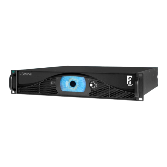
5. Overview ____________________________________________________ Front panel 1) Mounting ears 19” rack mounting 2) USB port USB Host A port – for all USB storage devices 3) TFT Display Full Colour display with touch screen* 4) Encoder Multi Colour Encoder 5) Rack handle Use both handles for manual transportation * The touch screen incorporates a thin flexible sheet that may be damaged by sharp objects or heavy treatment. - Page 12 5. Overview ____________________________________________________ Rear panel ALC Sentinel User’s Manual. Rev. 1.5...
- Page 13 5. Overview ____________________________________________________ 1) Finger guard The finger guard protects the fan intake. Do not block this area, because it will the reduce the airflow. 2) Networked Audio Inputs 2,1 Connect two RJ-45 connectors and leads for the networked audio inputs. One lead is for redundancy. 3) AES/ EBU* inputs 2,1Connect your AES/ EBU signal source for channel 1 and 2 to the female XLR connector input 1 and connect your AES/ EBU signal source for channel 3 and 4 to the female XLR connector input 2.
-
Page 14: Connections
The output+ and sense+ wires are connected together at the loudspeaker+ terminal, and the output- and sense- wires are connected together at the loudspeaker- terminal. All Alcons loudspeaker cabinets are SIS pre-wired. If your loudspeakers are not prepared for SIS wiring you can connect the sense wires to the output wires at the loudspeaker input. - Page 15 6. Connections _________________________________________________ The Speakon® connector is wired as follows: Speakon® male plug viewed from the wiring side Use bridge mode when you want to combine the power of Output+ amplifier channel 1+2 or 3+4 into one loudspeaker load. Ouput – In bridge mode connect your loudspeaker with or without SIS Sense + to the channel 1 and channel 2 outputs (or channel 3 and 4)
- Page 16 6. Connections _________________________________________________ For a given loudspeaker impedance, the proportional power loss as a function of cable length and cable gauge is given in the next table: 1.5 mm 2.5 mm 4 mm 6 mm 1.5 mm 2.5 mm 4 mm 6 mm 5 meters 1.4 %...
-
Page 17: Operation
7. Operation ____________________________________________________ Power On/Off The mains AC power of the amplifier is switched on when the PowerCon is connected. Each setting is automatically stored in memory, 30 seconds after the last user change. It is advised, to switch the amplifier off only, 30 seconds after the last instruction / setting change (otherwise the setting change will not be stored);... - Page 18 7. Operation ____________________________________________________ Multi-colour LED encoder Fig 1 Fig 2 Fig 3 Fig 4 The rotary encoder features a Multi-colour LED, which shows the status of the amplifier.. White (fig.1) Normal operation White blinking Eq settings changed - with changing settings in the equaliser-section, the encoder will blink, indicating that changes have been made to the stored settings.
-
Page 19: Tab Section Overview
7. Operation ____________________________________________________ Touch screen menu The touch screen function is applied for (de-)activating of a selection on the menu screen. Through the rotary encoder a specific value can be set (turn) and can be confirmed (click). The menu is divided in different “Tab sections” under which a function-dedicated page is located. This guide relates to Sentinel amplified loudspeaker controllers with front firmware v1.3 7.1 Tab section: Overview In this section, an overview is given of the most important settings, as they have been selected. - Page 20 7. Operation ____________________________________________________ 7.1 Tab section: Overview Fig 5. All channels no signal present, gain muted, amplifier temperature normal Fig 6. All channels signal present Fig 7. Output signal clip channel 1, signal -16,5dB channel 2-4 ALC Sentinel User’s Manual. Rev. 1.5...
-
Page 21: Tab Section Gain
7. Operation ____________________________________________________ 7.2 Tab section: Gain In this section, the gain settings for each of the 4 channels can be entered; Via this Gain Tab section, or the Overview Tab section, this function can be “enabled”/”disabled” (muted) per channel. Each channel can be muted individually or in cluster;... - Page 22 7. Operation ____________________________________________________ 7.2 Tab section: Gain Fig 8. Output channels 3 and 4 muted Fig 9. Guidance on all channels Fig 10. Output gain clip on channel 1 ALC Sentinel User’s Manual. Rev. 1.5...
-
Page 23: Tab Section Eq
7. Operation ____________________________________________________ 7.3 Tab section: Eq In this section, the equalizing settings for each of the 4 channels can be entered; Via this Eq Tab section, or the Overview Tab section this function can be “enabled”/ ”disabled” (bypass) per channel. Per channel there are 6 free-configurable equalizing bands available: Controllable parameters are frequency (f), q-factor (q) and gain (g). - Page 24 7. Operation ____________________________________________________ 7.3 Tab section: Eq Fig 11. Equalizer section channel 1, band 1 parametric EQ enabled and active Fig 12. Equalizer section channel 1, band 2 enabled and bypassed Fig 13. Equalizer section channel 1, disabled Fig 14. Equalizer type selection . ALC Sentinel User’s Manual.
-
Page 25: Tab Section Delay
7. Operation ____________________________________________________ 7.4 Tab section: Delay In this section, the delay settings for each of the 4 channels can be entered; Via this Delay Tab section, or the Overview Tab section this function can be “enabled”/”disabled” per channel. The delay function can be set to “absolute”, with which delay values are set as actual absolute values, including the latency of the Sentinel (used when Sentinels are mixed with other amplifiers/delay devices). -
Page 26: Tab Section Presets
Each channel can be assigned a different system preset; This can be an Alcons system, but it is also possible to use the amplified loudspeaker controller as a “non-Alcons-specific” linear amplifier, through the “LINEAR” preset. Herewith, no system processing is activated, but all other processing functions (equaliser, delay, routing, gain) remain active. - Page 27 7. Operation ____________________________________________________ 7.5 Tab section: Presets Fig 17. Scroll bar for selecting the different system presets Fig 18. Bi-amp preset channel 1 disabling active control channel 2 ALC Sentinel User’s Manual. Rev. 1.5...
-
Page 28: Tab Section Routing
7. Operation ____________________________________________________ 7.6 Tab section: Routing In this section, the routing for each of the 4 channels can be selected; Through the 4x4 matrix, per channel (4) a choice is available of available inputs (4). Up to 4 inputs can be selected per channel (i.e. mixed-mono signal for subwoofers). In addition, analogue or digital (AES3) input signal can be selected (w. -
Page 29: Tab Section System
7. Operation ____________________________________________________ 7.7 Tab section: System In this section, there are the system parameters that can be read or set, that are not required for “daily” operational usage. Through separate sub-tabs, operational data read-outs can be displayed and changed. 7.7.1 Speaker - this section shows the measured speaker (system) impedance, per channel;... -
Page 30: Setup
7. Operation ____________________________________________________ 7.7 Tab section: System Fig 22. Set-up menu with setting options 7.7.3 Setup - in this section, different system functionalities can be set, like system lock, screensaver function (the “eye”), date/time and mute-setting options. (see fig.22) 7.7.4 Lock system - with pressing this button, the QWERTY keyboard pops-up, to enter a password code; Confirm code and the active tab switches to Overview tab, with which all tabs are locked and only the Mute buttons can be operated. -
Page 31: High Headroom/ Low Noise
7.7.8 Backlight brightness - this can be adjusted, in “manual” (with slider bar) or “automatic” (through light sensor behind the front panel); Both the brightness of the display and the Alcons logo are adjusted. (see fig.24) Fig 23. Mute preferences set-up menu Fig 24. -
Page 32: Oplog
7. Operation ____________________________________________________ 7.7 Tab section: System 7.7.11 Oplog - this “operation log” section shows the status of the different sections inside ALC. When the illuminated encoder indicates a certain color/status, the oplog shows the actual report on the system status. When selecting “oplog” the function status of the encoder is reset (red blinking to white). 7.7.12 Clean oplog - touching this button cleans the log files/messages on the display: It does NOT clean the internal logging of the Sentinel, as that (more extensive) data cannot be erased by the user. -
Page 33: Project
7. Operation ____________________________________________________ 7.7 Tab section: System 7.7.15 Project - the settings of all sections of the amplifier can be stored in a Project file / User preset. Up to 100 user presets can be stored internally; Each project can also be stored externally; For this, a USB stick needs to be plugged into the front-located USB connector. Through the QWERTY keyboard each project file can be renamed. -
Page 34: Remote Control Through A Vnc Client
7. Operation ____________________________________________________ 7.8 Remote Control through a VNC client The ALC Sentinel is equipped with a VNC server to access the display screen remotely. This can be useful to operate a number of ALC Sentinel amplifiers connected to a wired LAN. To access the VNC server, a VNC client must be installed on the remote device, this can be a laptop, desktop PC, smartphone or tablet which can run VNC client software. -
Page 35: Remote Control With The Virtual Encoder
7. Operation ____________________________________________________ 7.8.1 Remote Control with the Virtual Encoder™ Fig 29. Virtual encoder For touch screen devices, the ALC Sentinel display features a transparent button to activate a Virtual Encoder™. This allows you to change certain parameters that need the encoder motion. To activate this Virtual Encoder™, press the area next to the System tab(see arrow), this will then pop up the Virtual Encoder™. (see fig.29) To change for example the Q in the “Eq”... -
Page 36: Safety
8. Safety _______________________________________________________ Protection circuits Guidance This is the limiting of the amplifier output for the protection of the speaker (this can be excursion or RMS limiting); Thus works different for each speaker/preset. The scale runs from top to bottom; When yellow bar reaches the bottom, maximum compression/limiting is reached. It is not a problem when the gain reduction is activated, but the LF response and overall dynamics will be limited. -
Page 37: Service And Support
Summary Alcons Audio BV warrants the original purchaser and any subsequent owner of each new Alcons product, for a period of three years from the date of the original purchase by the original purchaser that the new Alcons product is free of defects in materials and workmanship. Alcons Audio BV warrants the new Alcons product regardless of the reason for failure, except as excluded in this warranty. - Page 38 9. Service and support ___________________________________________ Error log list When the illuminated encoder indicates a certain color/status, the oplog shows the actual report on the system status. Component Error type (oplog) Result Action by user Amp module Over voltage on V+ Amp module off, 1 second cycle None, unless it starts preventing normal operation then repair is required Over voltage on V-...
- Page 39 9. Service and support ___________________________________________ Contact information Mailing address: Alcons Audio BV De Corantijn 69 1689 AN ZWAAG The Netherlands Tel.: +31 (0)229 283090 Fax.: +31 (0)229 283099 World Wide Web: http://www.alconsaudio.com E-mail: info@alconsaudio.com ALC Sentinel User’s Manual. Rev. 1.5...
-
Page 40: Specifications
10. Specifications _______________________________________________ ALC Sentinel 3 Input sensitivity for max RMS power __________________________________________________________________________ 1.22 Vrms / +3.9 dBu Maximum input level __________________________________________________________________________________________ +24 dBu Input impedance __________________________________________________________________________________44 kOhm balanced Input CMRR @ 1 kHz ____________________________________________________________________________________ 67 dB Frequency response all loads _______________________________________________________________________ 0 Hz – 50kHz +0 /-3 dB Gain ________________________________________________________________________________________ 32 dB / 40x Channel separation... - Page 41 10. Specifications _______________________________________________ ALC Sentinel 10 Input sensitivity for max RMS power __________________________________________________________________________ 2.12 Vrms / +8.7 dBu Maximum input level __________________________________________________________________________________________ +24 dBu Input impedance __________________________________________________________________________________44 kOhm balanced Input CMRR @ 1 kHz _____________________________________________________________________________________ 67 dB Frequency response all loads _____________________________________________________________________ 10Hz – 60kHz +0dB, -3dB...
-
Page 42: Block Diagram
11. Block diagram ______________________________________________ ALC Sentinel User’s Manual. Rev. 1.5... -
Page 43: Block Diagram Bridge Mode - Alc Sentinel 3 Only
11. Block diagram Bridge mode ___________________________________ ALC Sentinel User’s Manual. Rev. 1.5... -
Page 44: Ce Declaration Of Conformity
De Corantijn 69 1689 AN ZWAAG The Netherlands States that the following products: ALC Sentinel 3 ALC Sentinel 10 Are in conformity with the provisions of: Low Voltage Directive, 2006/95/EC Electro-Magnetic Compatibility Directive, 2004/108/EC Applied rules and standards: EN60065 (Electrical Safety) - Page 45 Notes _________________________________________________________ ALC Sentinel User’s Manual. Rev. 1.5...
Need help?
Do you have a question about the Sentinel 3 and is the answer not in the manual?
Questions and answers