Table of Contents
Advertisement
AQV18PSBN
AQV24PSBN
AQV18PSBX
AQV24PSBX
Basic Model
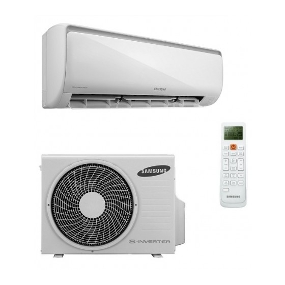
AQV18UGAN
AQV24UGBN
Model Code
AQV18PSBN
AQV24PSBN
High Efficiency
THE FEATURE OF PRODUCT
Air Conditioner
Mode
Mode can help you sleep quickly and
soundly and wake up refreshed.
Silence Mod
W
h
n e
o y
u
u
e s
h t
" e
experience extremely quiet operation of your
air conditioner.
AQV18UGAX
AQV24UGBX
AQV18PSBX
AQV24PSBX
l i S
n e
e c
M
o
d
, " e
o y
u
can
Advertisement
Table of Contents

Related Manuals for Samsung AQV18UGAN


Summarization of Contents
1. Precautions
1-1 Installing the air conditioner
Guidelines for installing the air conditioner.
1-2 Power supply and circuit breaker
Details on power supply and circuit breaker requirements.
1-3 During operation
Instructions for operating the air conditioner.
1-4 Disposing of the unit
Procedures for safely disposing of the unit.
1-5 Others
Miscellaneous precautions.
2. Product Specifications
2-1 The Feature of Product
Highlights key features and benefits of the product.
2-2 Product Specifications
Detailed technical specifications for the product.
2-3 The Comparative Specifications of Product
Compares specifications across different product models.
2-4 Accessory and Option Specifications
Specifications for accessories and optional components.
9. Circuit Descriptions
9-1 PCB Circuit Descriptions
Detailed descriptions of Printed Circuit Board (PCB) circuits.
9-2 Refrigerating Cycle Diagram
Diagram illustrating the refrigerant cycle of the unit.
10. PCB Diagram
10-1 Indoor PCB
Diagram showing the layout of the indoor PCB.
10-2 Outdoor PCB
Diagram showing the layout of the outdoor PCB.
11. Operating Instructions
11-1 Name of Each Part
Identifies and names the key parts of the unit.
11-2 Wireless Remote Control-Buttons and Display
Explains the functions of remote control buttons and display.
11-3 Main Function
Overview of the primary operational functions of the unit.
13. Block Diagram
13-1 Indoor Unit
Block diagram showing the internal structure of the indoor unit.
13-2 Outdoor Unit
Block diagram showing the internal structure of the outdoor unit.
14. Reference Sheet
14-1 Index for Model Name
An index to help locate information by model name.
14-2 Low Refrigerant Pressure Distribution
Chart showing refrigerant pressure distribution.
14-3 Pressure & Capacity mark
Table for converting pressure and capacity units.
14-4 Q & A for Non-trouble
Frequently asked questions for non-trouble related issues.
14-5 Cleaning/Filter Change
Instructions for cleaning and changing air filters.
14-6 Installation
Guidelines and procedures for installing the unit.
14-7 Installation Diagram of Indoor Unit and Outdoor Unit
Diagrams illustrating the installation process.
15. WORKING RANGE
15-1 Power Supply
Specifications for the unit's power supply requirements.
15-2 Working Range
Defines the operational temperature and humidity ranges.
5. Exploded Views and Parts List
5-1 Indoor Unit
Exploded view and parts list for the indoor unit.
Exploded Views and Parts List
5-2 Outdoor Unit
Exploded view and parts list for the outdoor unit.
8. Schematic Diagram
8-1 Indoor Unit
Schematic diagram for the indoor unit.
Schematic Diagram
8-2 Outdoor Unit
Schematic diagram for the outdoor unit.
4. Disassembly and Reassembly
Necessary Tools
Lists the tools required for disassembly and reassembly.
Disassembly and Reassembly
4-1 Indoor Unit
Step-by-step procedure for disassembling the indoor unit.
Disassembly and Reassembly
4-2 Outdoor Unit
Step-by-step procedure for disassembling the outdoor unit.
12. Troubleshooting
12-1 Items to be checked first
Initial checklist for troubleshooting common issues.
3. Alignment and Adjustments
3-1 Test Mode
Instructions on how to enter and operate the test mode.
Alignment and Adjustments
3-2 Display Error and Check Method
Methods for checking and interpreting display errors.
Alignment and Adjustments
3-3 Setting Option Setup Method
Guide for setting product options using the remote control.
13. Block Diagram
13-1 Indoor Unit
Block diagram showing the internal structure of the indoor unit.
Block Diagram
13-2 Outdoor Unit
Block diagram showing the internal structure of the outdoor unit.
7. Wiring Diagram
7-1 Indoor Unit
Wiring diagram for the indoor unit.
Wiring Diagram
7-2 Outdoor Unit
Wiring diagram for the outdoor unit.
11. Operating Instructions
11-1 Name of Each Part
Identifies and names the key parts of the indoor unit.
Operating Instructions
11-1-2 Outdoor Unit
Identifies and names the key parts of the outdoor unit.
Operating Instructions
11-2 Wireless Remote Control-Buttons and Display
Explains the functions of remote control buttons and display.
14. Reference Sheet
14-1 Index for Model Name
An index to help locate information by model name.
Reference Sheet
14-2 Low Refrigerant Pressure Distribution
Chart showing refrigerant pressure distribution.
Reference Sheet
14-3 Pressure & Capacity mark
Table for converting pressure and capacity units.
Reference Sheet
14-4 Q & A for Non-trouble
Frequently asked questions for non-trouble related issues.
14-5 Cleaning/Filter Change
14-5-1 Cleaning your Air Conditioner
Instructions for cleaning the air conditioner.
Cleaning/Filter Change
14-5-2 Cleaning Deodorizing and Bio Filter (Option)
Guide for cleaning optional filters.
14-6 Installation
14-6-1 Before Installation
Preliminary steps and considerations before installation.
14-6-2 Installation Procedure
Step-by-step guide for product installation.
14-7 Installation Diagram of Indoor Unit and Outdoor Unit
14-7-1 Air-Purge Procedure
Steps for air purging during installation.
Installation Diagram of Indoor Unit and Outdoor Unit
14-7-2 "Pump down" Procedure
Procedure for pump down operation.
15. POWER SUPPLY
15-1 Power Supply
Specifications for the unit's power supply requirements.
15-2. WORKING RANGE
15-2-1. MULTIZONE/MONOZONE/SUMMIT
Working range for MULTIZONE models.
WORKING RANGE
15-2-2. BIGFLOW
Working range for BIGFLOW models.
Need help?
Do you have a question about the AQV18UGAN and is the answer not in the manual?
Questions and answers