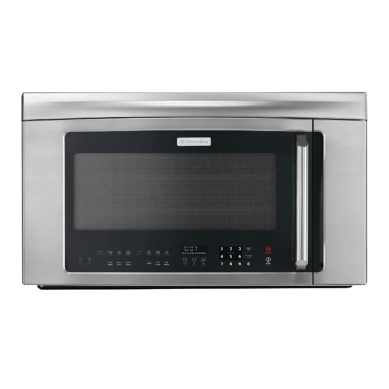
Electrolux EI30BM55HS - Microwave Technical & Service Manual
Hide thumbs
Also See for EI30BM55HS - Microwave:
- Specification sheet (2 pages) ,
- Installation instructions manual (25 pages) ,
- Use & care manual (36 pages)
Table of Contents
Advertisement
Advertisement
Table of Contents
Troubleshooting

Summarization of Contents
Section 1 Basic Information
Safe Servicing Practices
Guidelines for performing safe maintenance and repairs on the appliance.
Warnings and Safety Information
Crucial warnings and general safety information for service personnel.
Precautions for Microwave Energy Exposure
Measures to avoid exposure to microwave radiation during servicing.
High Voltage Dangers
Alerts regarding high voltage hazards within the microwave oven.
Before Servicing Procedures
Steps to follow before commencing any service or maintenance tasks.
Microwave Measurement Procedure
Methodology for testing microwave leakage and emissions.
Product Specifications
Technical details and features of the microwave oven model.
Grounding Instructions
Proper procedures for grounding the appliance for electrical safety.
Oven Diagram
Visual representation of the microwave oven's components and layout.
Section 2 Operation
Operating Sequence Description
Detailed explanation of the oven's sequence of operations during use.
Variable Cooking Power
Explanation of how variable power levels are managed during cooking.
Sensor Cooking Conditions
Information on how the sensor cooking function works and its sequence.
Hot Air Exhaust Ventilation Methods
Description of different methods for venting hot air from the oven.
Oven Schematics
Electrical schematics illustrating oven conditions during operation.
Component Descriptions
Detailed explanation of individual microwave oven components.
Touch Control Panel Operation
How to operate the microwave using the touch control panel interface.
Humidity Sensor Circuit
Explanation of the humidity sensor's function and circuit operation.
Section 3 Troubleshooting and Testing
Troubleshooting Guide
General guidance and steps for diagnosing oven problems.
Troubleshooting Guide Chart
A chart mapping problems to possible causes and tests.
Test Procedures
Detailed procedures for testing specific oven components.
Magnetron Assembly Test
Procedure to test the magnetron assembly for proper function.
Microwave Output Power Test
Test to measure microwave output power using a water temperature rise.
Power Transformer Test
Procedure for testing the power transformer's continuity and resistance.
High Voltage Rectifier Test
Test to check the high voltage rectifier for shorts or open circuits.
High Voltage Capacitor Test
Procedure to test the high voltage capacitor for shorts or opens.
Thermal Cut-Out and Temperature Fuse Tests
Tests for cavity thermal cut-out and magnetron temperature fuse.
Interlock Switch and Relay Tests
Procedures for testing door sensing, interlock, and primary relays.
Monitor Switch and Fuse Tests
Tests for the monitor switch and procedures for blown monitor fuse.
Hood Thermostat and Fan Motor Tests
Tests for hood thermostat operation and hood fan motor functionality.
Touch Control Panel Assembly Test
Troubleshooting procedures for the touch control panel assembly.
Keyboard Glass Unit Test
Procedure to test the keyboard glass unit for proper key input.
Relay Tests (RY1 and RY2)
Tests for the primary interlock relay (RY2) and other relays.
Printed Wiring Board (PWB) Fuse Test
Procedure for checking and replacing the fuse on the PWB.
Humidity Sensor Test
Test procedures to diagnose humidity sensor and control unit issues.
Noise Filter Test
Procedure to test the noise filter for proper operation.
Section 4 Component Teardown
Servicing Precautions
Important precautions for handling electronic components during servicing.
Touch Control Panel Servicing
Procedures for servicing the touch control panel assembly.
Soldering and Tool Usage
Guidelines for soldering and using specific tools for repairs.
High Voltage and Microwave Energy Warnings
Critical warnings about high voltage and microwave energy hazards.
General Precautions Before Wiring
Safety precautions to follow before performing any wiring or electrical work.
Oven Removal from Wall
Step-by-step instructions for safely removing the oven from its wall mounting.
Hood Louver Removal
Procedure for removing the hood louver assembly.
Outer Case Removal
Instructions for removing the outer case cabinet of the microwave oven.
Magnetron Removal
Procedure for safely removing the magnetron component.
High Voltage Rectifier and Capacitor Removal
Steps for removing the high voltage rectifier and capacitor.
Hood Fan Motor, Duct, Lamp Socket, Humidity Sensor Replacement
Procedures for replacing hood fan motor, duct, lamp socket, and humidity sensor.
Power Transformer Removal
Detailed steps for removing the power transformer.
Hood Fan Thermostat Removal
Procedure for removing the hood fan thermostat (60°C ON/70°C OFF).
Turntable Motor Removal
Steps for removing the turntable motor.
Cooling Fan Motor Removal
Procedure for safely removing the cooling fan motor.
Positive Lock Connector Removal
Instructions for removing the positive lock connector.
Oven Lamp Removal
Procedure for removing the oven lamp.
Cook Top Lamp Socket Removal
Steps for removing the cook top lamp socket.
Stirrer Antenna Motor Removal
Procedure for removing the stirrer antenna motor.
Stirrer Cover and Antenna Installation
Instructions for installing the stirrer cover and antenna.
Right Panel and Power Unit Removal
Procedure for removing the right panel assembly and power unit.
Door Switch Removal and Adjustment
Steps for removing and adjusting door sensing, interlock, and monitor switches.
Door Switch Adjustment Details
Detailed adjustment procedure for door sensing, interlock, and monitor switches.
Door Replacement
Procedure for replacing the microwave oven door assembly.
Door Disassembly
Steps to disassemble the microwave oven door.
Section 5 Wiring Diagrams
Pictorial Diagram
A visual diagram showing the layout of components and wiring.
Power Unit Circuit
Schematic diagram of the power unit circuit board.
Glass Touch Key and Display Unit Circuit
Wiring diagram for the glass touch key unit and display unit.
Printed Wiring Board Layout
Diagram showing the layout of components on the printed wiring board.


Need help?
Do you have a question about the EI30BM55HS - Microwave and is the answer not in the manual?
Questions and answers