Table of Contents
Advertisement
Service Manual
Specifications
(Information in brackets [ ] refers to model 32")
Power Source:
Power Consumption
Stand-by Power Consumption: 0.3W (Without monitor out recording)
Aerial Impedance:
Receiving System:
Receiving Channels:
Operating Conditions:
220-240V AC, 50Hz
130W [115W]
13W (With monitor out recording)
75Ω unbalanced, Coaxial Type
U10B
PAL-I
PAL-525/60 (AV only)
DVB-T (via UHF aerial input)
M.NTSC (AV only)
NTSC (AV only)
U10B
UHF E21-E68
0°C ÷ 35°C
Temperature:
Humidity: 20% ÷ 80% RH (non condensing)
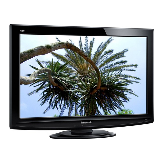
Colour LCD Television
GLP24 Chassis
U10E
PAL-I/H, B/G, D/K
SECAM B/G, D/K, L/L'
PAL-525/60 (AV only)
DVB-T (Digital Terrestrial Services)
DVB-C (Digital cable services)
M.NTSC (AV only)
NTSC (AV only)
U10E
VHF E2-E12
VHF A-H (ITALY)
VHF R3-R5
UHF E21-E69
CATV S1-S10 (M1-M10)
CATV S21-S41 (Hyperband)
ORDER No. PCZ0906109CE
TX-L32U10B
TX-L32U10E
TX-L37U10B
TX-L37U10E
VHF H1-H2 (ITALY)
VHF R1-R2
VHF R6-R12
CATV (S01-S05)
CATV S11-S20 (U1-U10)
© Panasonic Corporation 2009.
Unauthorized copying and
distribution is a violation of law.
Advertisement
Table of Contents

Summarization of Contents
Product Specifications
Power, Receiving Systems, and Channels
Details power requirements, supported broadcast standards, and channel frequencies.
Connectivity and Physical Specifications
Terminals, Connectivity, and Physical Data
Describes input/output ports, connectivity options, dimensions, and weight.
Safety Precautions
General Service Guidelines
Provides basic safety rules for servicing the unit.
Electrical Safety Checks
Details touch current check procedure and safety testing methods.
Electrostatic Discharge (ESD) Prevention
ESD Sensitive Device Handling
Explains methods for safely handling sensitive electronic components.
Materials and Soldering Information
Lead Free Solder (PbF) Details
Provides information on lead-free solder usage, handling, and types.
Applicable Signals
Signal Compatibility Overview
Lists supported video signal formats and PC timing compatibility.
Service Hints
Disassembly Procedures
Guides on removing the back cover and pedestal for component access.
Chassis and Board Layout
Board Identification and Functions
Identifies main boards and their primary functions within the chassis.
Lead Wiring Connections
Shows routing and connection points for internal wiring harnesses.
Setting Inspection
Voltage Confirmation Points
Lists test points and expected voltage values for verification during inspection.
Self-Check Functionality
Entering and Using Self-Check Mode
Instructions on how to access and operate the self-check feature for diagnostics.
Power LED Blinking Timing Chart
Interpreting Power LED Fault Codes
Links LED blinking patterns to specific error conditions and diagnostic information.
Service Mode Functionality
How to Enter Service Mode
Describes the specific procedure to access the unit's service menu.
Service Mode Adjustments
Key Commands for Service Adjustments
Explains button functions for navigating and adjusting settings within the service menu.
Adjustment Flow and Storage
Details the process of making, confirming, and saving adjustments.
Option Bytes Description
Configuration Options Overview
Explains various programmable option bytes and their settings for customization.
Adjustment Methods
Sub-Contrast and White Balance Calibration
Covers procedures for adjusting contrast and white balance for optimal picture quality.
Wiring Diagram
Board-to-Board Connectivity
Illustrates interconnectivity between major system boards for signal routing.
Video & Stereo Audio Block Diagram
Audio Processing Signal Flow
Visualizes the signal flow for audio processing from input to output.
Power Supply Block Diagram
Power Distribution Overview
Shows how power is supplied to different internal components from the power supply unit.
Control System Block Diagram
System Control Signal Flow
Depicts the flow of control signals within the TV for system operation.
Parts Location
Exploded View of Components
Identifies physical locations of parts using numbered diagrams for easy reference.
Replacement Parts List
Common Parts Identification
Lists general components like speakers, tuners, cables, and accessories.
ICs, Diodes, Transistors, and Resistors
Details specific ICs, diodes, transistors, and resistors with part numbers.
Schematic Diagrams
Schematic Diagram Notes and Symbols
Explains conventions, symbols, and general notes for reading schematics.
Safety Remarks for Schematic Work
Provides crucial safety warnings related to working with schematics and high-voltage circuits.


Need help?
Do you have a question about the Viera TX-L32U10E and is the answer not in the manual?
Questions and answers