
Related Manuals for multimatic MD-2000I


Summary of Contents for multimatic MD-2000I
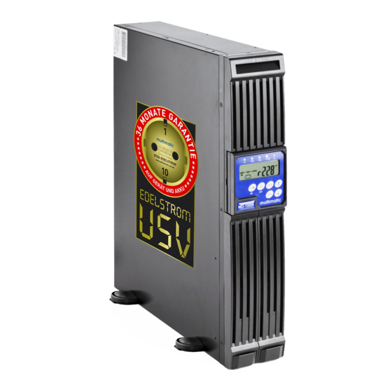
- Page 1 Uninterruptible Power Supply MD-1000I / MD-2000I / MD-3000I V 1.0 User Manual Authentic Manual...
- Page 2 Imprint Imprint multimatic Vertriebs GmbH This document is protected by copyright held by multimatic Vertriebs GmbH, 78667 Villingendorf, Germany. This document is intended solely for the operator and operator's personnel. Any reproduction, distribution, commercial or competitive use of its contents (text, graphic representations, including figures, drawings, images schematics, etc.), or making of them available to a third party, whether in part or in their en-...
- Page 3 MD-1000I / MD-2000I / MD-3000I Imprint multimatic Vertriebs GmbH reserves the right to make cosmetic or technical design changes that may serve to improve the system, manufacturing process or the product. MD Series...
-
Page 4: Table Of Contents
MD-1000I / MD-2000I / MD-3000I Table of Contents Table of Contents Introduction ........................ 6 Forward ........................6 Scope of Application ....................7 Availability of Manual ....................7 Symbols Used in Manual ..................... 7 ... - Page 5 MD-1000I / MD-2000I / MD-3000I Table of Contents System Operation and Display ................64 UPS Modes and Display Messages ................64 USP User Instructions....................64 Replacing Batteries.....................72 Trouble Shooting Guide ...................77 ...
-
Page 6: Introduction
MD-1000I / MD-2000I / MD-3000I Introduction Introduction Forward Dear User, You will find this manual to be of great assistance. For this reason, we urge you to read it carefully before operating the unit. It will provide you with information and instructions necessary to effectively and responsibly operate the uninterruptible power supply. -
Page 7: Scope Of Application
The explanations found in this manual apply exclusively for the uninterruptible power supply as described in the Technical Information section as an entire system and for modules, subsystems and individual parts designed and built by multimatic Vertriebs GmbH. ( 11. Technical Information) - Page 8 MD-1000I / MD-2000I / MD-3000I Introduction Text in which "WARNING!" appears warns you of dangers. If you neglect preventative measures, serious (irreversible), life-threatening injuries or death may occur! Text in which "CAUTION!" appears warns you of dangers. If you neglect precautionary measures, slight or moderate injuries may occur! Text in which "ATTENTION!"...
- Page 9 MD-1000I / MD-2000I / MD-3000I Introduction 1.4.2 Warning pictograms 1.4.2.1 Hazard vicinity warning Generally hazardous area! 1.4.2.2 Specific warnings Hazardous voltage! Battery hazard! 1.4.3 Mandatory action symbols Take action as stated in information and instructions provided in docu- ments and by pictograms.
- Page 10 MD-1000I / MD-2000I / MD-3000I Introduction 1.4.4 General symbols This symbol indicates actions that you are required to perform. This hyphen introduces items in a list. This arrow indicates a cross reference. To keep things easily understandable, you'll find cross references directing you to other chapters on occasion.
-
Page 11: Information Liability
– those responsible for disposal and recycling of the device. They must understand and follow every instruction and all guide- lines provided therein. multimatic Vertriebs GmbH accepts no liability for damages caused by uninstructed or insufficiently instructed personnel! Warranty Terms Your receipt is your proof for your initial purchase. - Page 12 In general, the warranty does not cover shipping costs. The customer is responsible for repair and replacement costs and multimatic Vertriebs GmbH is not liable for damages, whether direct, accidental, unique or consequential damage, even if caused by negligence or other acts.
-
Page 13: Transport And Storage
Liability limitations Claims for compensation are excluded, unless based on wrongful intent or gross negligence on the part of multimatic Vertriebs GmbH or its employees. Liability as per product liability laws remains unaffected. Under no circum- stances are we liable for: –... -
Page 14: Installation Site
MD-1000I / MD-2000I / MD-3000I Introduction Installation Site Do not install in an area where flammable vapours are present, for exam- ple, petrol/gasoline, storerooms, areas in which combustion-driven mo- tors operate, etc. The UPS appliance is designed for operation in ventilated rooms with ambient temperatures of 0 to 40°... - Page 15 MD-1000I / MD-2000I / MD-3000I Introduction MD Series...
-
Page 16: Safety Instructions
MD-1000I / MD-2000I / MD-3000I Safety Instructions Safety Instructions Introduction The UPS is designed and built in accordance with technical guidelines and regulations for uninterruptible power supply equipment. It and its components, modules and assemblies individually and as an entire sys- tem meet the current safety code requirements and comply with the EU 2006/42/EG Machinery Directive. -
Page 17: Avoiding Personal Injury And Property Damage
Perform only the service and maintenance work that is described in the pro- vided documents. Follow the stipulated actions and steps as described. Use only original parts obtained from multimatic Vertriebs GmbH. Environmental Protectio When your product has reached the end of its service life, send it back to mul- timatic Vertriebs GmbH and we'll dispose of it compliant with environmental protection laws. -
Page 18: Power Connection
MD-1000I / MD-2000I / MD-3000I Safety Instructions Power Connection Use only an outlet socket with earthed/grounding contact or, if using a terminal block, connect protective conductor. Under no circumstances, operate the UPS without an earth/ground connection. The socket you use must be readily accessible and close to the UPS unit. -
Page 19: Operation
MD-1000I / MD-2000I / MD-3000I Safety Instructions Operation Before connecting equipment to the UPS outlet, you must perform the initial configuration. Very important here is the output voltage going to the connected equipment. The UPS device contains an energy storage facility (battery), which means the outlet can carry electricity even if the USP is not connected to a power supply. -
Page 20: Maintenance, Service And Malfunction
MD-1000I / MD-2000I / MD-3000I Safety Instructions Defective batteries must be disposed of compliant with environmental protection regulations. Under no circumstances ever dispose of batteries with regular household garbage. Follow local disposal regulations. Maintenance, Service and Malfunction Attention! Danger of shock Even after, you have turned off the power switch or broken the circuit to the battery, UPS components may still carry high voltage. - Page 21 MD-1000I / MD-2000I / MD-3000I Safety Instructions MD Series...
-
Page 22: Explanation Of Usb Function
MD-1000I / MD-2000I / MD-3000I Explanation of USB Function Explanation of USB Function This manual will provide you with fundamental information about single-phase online UPS systems, specifically how they function, use of the various func- tions and what you are to do in the event of malfunction. In addition, this man- ual contains information about transport, storage, handling and installation of UPS systems. - Page 23 MD-1000I / MD-2000I / MD-3000I Explanation of USB Function The advanced insulated-gate bipolar transistor (IGBT) technology and indus- trial quality design ensure the UPS will operate efficiently and dependably, even under tough conditions. A powerful CPU integrates all the power stages, control and communication...
-
Page 24: Front Panel
Explanation of USB Function Front Panel You'll find all the display and control elements you need for normal use on the UPS' front panel. Status LEDs LCD display Buttons Fig. 3-1 - 1 MD-1000I / MD-2000I / MD-3000I front view MD Series... - Page 25 MD-1000I / MD-2000I / MD-3000I Explanation of USB Function 3.1.1 LCD display (optional) LCD display LED input voltage Programmable output 1 LED Programmable output 2 LED Bypass LED UPS system fault LED Select Scroll up Scroll down 10 Other functions 11 UPS off 12 UPS on;...
- Page 26 MD-1000I / MD-2000I / MD-3000I Explanation of USB Function 3.1.2 Keypad UPS On / Alarm mute (12) functions: Turns UPS on. Deactivates audible alarm. UPS off (11) functions: Turns UPS off. Other functions (10) functions: Buzzer on/off ...
- Page 27 MD-1000I / MD-2000I / MD-3000I Explanation of USB Function Manual bypass To activate the manual bypass, proceed as follows: Press buttons 12 and 8 simultaneously for about 3 seconds, to change from normal operation to bypass mode. The LED bypass indicator will blink constantly and an audible signal will sound.
- Page 28 MD-1000I / MD-2000I / MD-3000I Explanation of USB Function 3.1.3 LCD display panel symbols Item Symbol Description Power supply (utility) or bypass source Battery low Battery problem Output overload Local wire problem UPS shut off Abnormal UPS lock UPS flow...
-
Page 29: Rear Panel
Explanation of USB Function Rear Panel 3.2.1 MD-1000I USB port Battery pack connector Power input Communication interface Two programmable outputs UPS output Input circuit breaker Emergency power off (EPO) port 10 RS-232 port Fig. 3-2 - 3 MD-1000I rear panel MD Series... - Page 30 MD-1000I / MD-2000I / MD-3000I Explanation of USB Function When the USP output and power input sockets are in connected states, they are capable of transmitting power. Even if disconnected, dangerous electrical charges may be present in- side the unit that could discharge hazardous high voltage at the connec- tions.
- Page 31 MD-1000I / MD-2000I / MD-3000I Explanation of USB Function 3.2.2 MD-2000I USB port Battery pack connector Input circuit breaker Power input Communication interface UPS output (non-programmable) UPS output (programmable) Emergency power off (EPO) port 10 RS-232 port Fig. 3-2 - 4 MD-2000I rear panel...
- Page 32 MD-1000I / MD-2000I / MD-3000I Explanation of USB Function When the USP output and power input sockets are in connected states, they are capable of transmitting power. Even if disconnected, dangerous electrical charges may be present in- side the unit that could discharge hazardous high voltage at the connec- tions.
- Page 33 MD-1000I / MD-2000I / MD-3000I Explanation of USB Function 3.2.3 MD-3000I 4 5 5 6 USB port Battery pack connector Circuit breaker for two programmable outputs Circuit breaker for two non-programmable outputs Power input circuit breaker Power input Communication interface...
- Page 34 MD-1000I / MD-2000I / MD-3000I Explanation of USB Function When the USP output and power input sockets are in connected states, they are capable of transmitting power. Even if disconnected, dangerous electrical charges may be present in- side the unit that could discharge hazardous high voltage at the connec- tions.
-
Page 35: Ups Output
MD-1000I / MD-2000I / MD-3000I Explanation of USB Function 3.2.4 UPS output IEC 10 A socket for equipment connection The protective earth conductor must be connected! Make sure you observe the input voltage requirements that appear on the identification label and in the technical information provided in this man- ual. - Page 36 MD-1000I / MD-2000I / MD-3000I Explanation of USB Function 3.2.6 Relay card (potential-free) Fig. 3-2 - 6 Relay card (potential-free) Pin configuration: UPS in bypass mode (Bypass) Normal power source (normal: closed contact) Normal power source (normal: open contact) Inverter on...
-
Page 37: Usb Port
MD-1000I / MD-2000I / MD-3000I Explanation of USB Function The shutdown function activates after +6~+25VDC between PIN 9 and Pin 10 is applied for 5 seconds. Each relay contact has a load capacity of 40VDC/25mA. Installation: random insert. Flexible output for N.C. (normal closed) or N.O. (normal open) Sets via the repositioning of Jumper Pin1-2 or Pin2-3 from JP1-5. - Page 38 MD-1000I / MD-2000I / MD-3000I Explanation of USB Function 3.2.9 Fan cools UPS. 3.2.10 Power input IEC power plug MD-1000/2000 - C13/10A MD-3000 - C19/16A The unit connects to the power supply by means of the enclosed power cable with Schuko plug.
- Page 39 MD-1000I / MD-2000I / MD-3000I Explanation of USB Function 3.2.11 RS-232 port PIN 3: RS-232 Rx PIN2: RS-232Tx PIN5: Earth/Ground Fig. 3-2 - 8 RS-232 ports MD Series...
-
Page 40: Installation Changes
MD-1000I / MD-2000I / MD-3000I Explanation of USB Function Installation Changes The UPS features placement versatility to accommodate specific needs: Vertical standing on feet Horizontal in 19" rack Depending on your chosen means of installation, you will need to turn the LCD display (tower) or mount brackets to the unit (19"... - Page 41 MD-1000I / MD-2000I / MD-3000I Explanation of USB Function Make sure the floor under the UPS is even and level. The floor must have sufficient weight-bearing capacity. For specific weight-bearing requirements, you'll find the UPS weight in the technical information ( Chapter 11 Technical Information) Turning the display: Fig.
-
Page 42: Rack Installation
MD-1000I / MD-2000I / MD-3000I Explanation of USB Function 3.3.2 Rack installation Fig. 3-3 - 3 Rack installation Proceed as described in the following: Turn the display, so you can read it when the unit is in the rack. - Page 43 MD-1000I / MD-2000I / MD-3000I Explanation of USB Function Fig. 3-3 - 4 Rack brackets Mount the brackets to both sides of the housing. MD Series...
- Page 44 MD-1000I / MD-2000I / MD-3000I Explanation of USB Function Fig. 3-3 - 5 19"-rack Insert the UPS into the 19"-rack. MD Series...
- Page 45 MD-1000I / MD-2000I / MD-3000I Explanation of USB Function Screws Fig. 3-3 - 6 Fixing the UPS in the 19"-rack Use the screws (1) to fasten the UPS to the rack. Upon completion, you may connect the UPS and put it into operation.
-
Page 46: Operational Modes And Voltage Settings
MD-1000I / MD-2000I / MD-3000I Explanation of USB Function Operational Modes and Voltage Settings Download the UPS Setting Tool software and open the software, so that you have the window shown below open. System configuration settings 1. Selecting power supply voltage: Select the input voltage 230V. - Page 47 MD-1000I / MD-2000I / MD-3000I Explanation of USB Function 6. Syn-Frequency Window: Select 3Hz/1Hz inverter frequency range 7. Com. port: Select the PC’s communication port 8. Click Write to confirm the configuration settings. The UPS sounds two audi- ble tones to indicate you have successfully made the settings.
- Page 48 MD-1000I / MD-2000I / MD-3000I Explanation of USB Function Programmable output settings To meet the power needs of less critical equipment, the UPS comes with 2 programmable outputs. You can deactivate these outputs to shut down less critical equipment while the UPS is running on the battery or to reduce the load in order to ensure the critical equipment will continue to receive power.
- Page 49 MD-1000I / MD-2000I / MD-3000I Explanation of USB Function 1. "Outlet turn on, after UPS on" allows you to set the time delay. Set the delay between the time when the UPS turns on and the time when the output automatically activates.
-
Page 50: Storage And Unpacking
MD-1000I / MD-2000I / MD-3000I Storage and Unpacking Storage and Unpacking UPS Storage If you don't put the UPS into operation immediately, you need to follow the in- structions below: Always store the unit and any accessories in their original packaging. - Page 51 MD-1000I / MD-2000I / MD-3000I Storage and Unpacking MD Series...
-
Page 52: System Function
MD-1000I / MD-2000I / MD-3000I System Function System Function The UPS operates continuously employing double conversion online topology. It processes the power provided by the power source, providing uninterrupted, clean, single-phase power for the critical equipment. Besides furnishing the connected equipment with power, the UPS charges the internal battery, keeping it charged to its capacity. - Page 53 MD-1000I / MD-2000I / MD-3000I System Function Important UPS components are: – AC to DC power converter (rectifier) – AC to DC high frequency power inverter – Smart battery charger – String consisting of durable maintenance-free batteries – DC to DC push-pull inverter –...
-
Page 54: Ups Operating Mode - Normal
MD-1000I / MD-2000I / MD-3000I System Function UPS Operating Mode - Normal Normal UPS operation is as shown below: Fig. 5-2 - 1 During normal power supply The inverter converts DC into clean, stable AC. Output LEDs 2 and 4 light. - Page 55 MD-1000I / MD-2000I / MD-3000I System Function Abnormal UPS operation is as shown below: Fig. 5-2 - 2 During abnormal power supply If the power supply is abnormal, the UPS battery automatically transmits power to the inverter, shuts off the charger and the AC-DC power converter (rectifier).
-
Page 56: Overload
MD-1000I / MD-2000I / MD-3000I System Function Overload UPS operation when overloaded is as shown below: Fig. 5-3 - 1 Overloaded situation Generally, modern electronics and IT equipment produce inrush current when they start. The magnitude of the inrush current varies depending on the equip- ment. -
Page 57: Inverter
MD-1000I / MD-2000I / MD-3000I System Function Inverter Fig. 5-4 - 1 Inverter malfunction Output short circuit If a short circuit occurs in the output while the connected equipment is receiv- ing current from the inverter, the UPS automatically shuts down the inverter and ceases supplying the equipment with power. -
Page 58: Inverter - Excessive Internal Temperature
MD-1000I / MD-2000I / MD-3000I System Function Inverter - Excessive Internal Temperature Raised temperatures in the UPS automatically set off the bypass mode. The UPS switches back over to normal operation, once the temperature has re- turned to normal. If excessive termperatures occur while the energy supply is abnormal, the audible alarm sounds and the LEDs indicate malfunction. - Page 59 MD-1000I / MD-2000I / MD-3000I System Function MD Series...
-
Page 60: Ups Installation And Hook-Up
MD-1000I / MD-2000I / MD-3000I UPS Installation and Hook-Up UPS Installation and Hook-Up All instructions in technical information pertaining to the operating environment and operating conditions are mandatory and necessary to the proper function and operation of the UPS. For the installation of the UPS in a tower or rack configuration, the following in- structions apply: –... - Page 61 MD-1000I / MD-2000I / MD-3000I UPS Installation and Hook-Up Power mains 16 A 1.5 mm Load 1 Load 2 Fig. 6-1 - 1 UPS and connected equipment connections MD Series...
-
Page 62: Ups Communication Interfaces
MD-1000I / MD-2000I / MD-3000I UPS Installation and Hook-Up UPS Communication Interfaces The UPS has convenient communication features for data transfer. Only a single communication port can be active. The USB port has priority over the RS-232 port. If a communication cable is connected, the software can exchange data with the UPS. -
Page 63: Equipment Connection Sequence
MD-1000I / MD-2000I / MD-3000I UPS Installation and Hook-Up Equipment Connection Sequence Connect the UPS to source of power, but make sure the power source and the UPS are both reliably shut down. Before connecting equipment to the UPS outlet, you must perform the ini- tial configuration. -
Page 64: System Operation And Display
MD-1000I / MD-2000I / MD-3000I System Operation and Display System Operation and Display UPS Modes and Display Messages Operating this system involves different operational modes and control com- munications. USP User Instruction The user of this UPS system must invariably follow and adhere to the in- structions and guidelines provided in this manual at all times. -
Page 65: Turning On The Ups
MD-1000I / MD-2000I / MD-3000I System Operation and Display 7.2.1 Turning on the UPS Connect the power cable to the UPS. The UPS starts. Fig. 7-2 - 1 UPS power cable connected Hold the button USV Ein down ( Fig. 3-1 - 2, Item 12) until the unit emits an audible alarm. -
Page 66: Turning Off The Ups
MD-1000I / MD-2000I / MD-3000I System Operation and Display Fig. 7-2 - 3 Main display If the system fails the self test, it will indicate failure on the LCD display. Figure. 7-2 - 4 Failure 7.2.2 Turning off the UPS Hold the button USV Aus down (... - Page 67 MD-1000I / MD-2000I / MD-3000I System Operation and Display 7.2.3 Menu 7.2.4 Readings With the Scroll Down ( Fig. 3-1 - 2, Item 9) Scroll Up ( Fig. 3-1 - 2, Item 8) keys, you can view the various values monitored by the system.
- Page 68 MD-1000I / MD-2000I / MD-3000I System Operation and Display Fig. 7-3 - 4 Output frequency Fig. 7-3 - 5 Capacity in use Fig. 7-3 - 6 Battery charging voltage Fig. 7-3 - 7 Temperature inside UPS MD Series...
- Page 69 MD-1000I / MD-2000I / MD-3000I System Operation and Display 7.2.5 Menu functions Press Other Functions ( Fig. 3-1 - 2, Item 10) to view the menu. Menu structure: Fig. 7-3 - 8 Audible signal ON / OFF Fig. 7-3 - 9 Run self test...
- Page 70 MD-1000I / MD-2000I / MD-3000I System Operation and Display Fig. 7-3 - 12 Inverter output voltage Fig. 7-3 - 13 UPS operating mode: Online, 50Hz or 60Hz at output Inverter output settings: Fig. 7-3 - 14 +1% -1%, +2% -2%, +3% -3%...
- Page 71 MD-1000I / MD-2000I / MD-3000I System Operation and Display Consult your dealer or specialist before you change the settings in this menu. Wrong settings may cause the system to malfunction or even damage the UPS irreparably. You'll find a description of the parameters in the following table.
-
Page 72: Replacing Batteries
MD-1000I / MD-2000I / MD-3000I System Operation and Display Replacing Batteries Risk of electrical shock Battery replacement must be performed by QUALIFIED SERVICE PER- SONNEL ONLY! Even when the UPS is turned off, the batteries and UPS components carry hazardous electrical charges. - Page 73 MD-1000I / MD-2000I / MD-3000I System Operation and Display Screws Fig. 7-4 - 2 Screws Remove both screws (1) MD Series...
- Page 74 MD-1000I / MD-2000I / MD-3000I System Operation and Display Front panel cover Fig. 7-4 - 3 Front panel cover Slide the front panel cover (1) to the left out of the housing. MD Series...
- Page 75 MD-1000I / MD-2000I / MD-3000I System Operation and Display Model MD-1000I Connector Fig. 7-4 - 4 MD-1000I Unplug the connector (1) Pull the battery out of the housing. MD Series...
- Page 76 MD-1000I / MD-2000I / MD-3000I System Operation and Display Model MD-2000I and MD-3000I Connector Fig. 7-4 - 5 MD-2000I and MD-3000I Unplug the connector (1) Pull both batteries out of the housing. MD Series...
-
Page 77: Trouble Shooting Guide
MD-1000I / MD-2000I / MD-3000I Trouble Shooting Guide Trouble Shooting Guide Only authorised qualified service personnel are to perform repairs or cor- rective actions to remedy UPS system malfunctions. Situation Description Audible Signal Description UPS malfunction, serious Long continuous audible signal... - Page 78 MD-1000I / MD-2000I / MD-3000I Trouble Shooting Guide Situation Malfunction Message Solution Meaning UPS failure LED 1. Check if the battery is properly 1. Er05 battery weak connected. Check battery voltage to or defective determine if the batteries are Read the failure code charged and free of defect.
- Page 79 MD-1000I / MD-2000I / MD-3000I Trouble Shooting Guide UPS doesn't provide If the back-up time is still shorter than interval time or time is required after charging for 8 hours, shorter than expected. please contact your local dealer for technical assistance.
- Page 80 MD-1000I / MD-2000I / MD-3000I Trouble Shooting Guide Malfunction code: Code Meaning Er05 Battery weak or defective Er06 Output short circuit Er07 EPO mode Er11 UPS under excessive temperature Er12 Inverter overload Er14 Fan defective Er18 EEPROM data error Er24 Power supply low (<85/170V) and battery not...
-
Page 81: Software
MD-1000I / MD-2000I / MD-3000I Software Software Connect the RS-232 or USB cable connector to the UPS communication port. Connect the RS-232 or USB cable socket to a suitable RS-232/USB com- puter port. A suitable software package can monitor and process UPS settings and opera- tional status via communication port. -
Page 82: Maintenance And Service
MD-1000I / MD-2000I / MD-3000I Maintenance and Service Maintenance and Service With just a little maintenance, you will have the uninterrupted use of your UPS system for a long time. Please note that the dependability of the UPS is very much affected by its envi- ronment. - Page 83 MD-1000I / MD-2000I / MD-3000I Maintenance and Service Remember that after the test the batteries are low. The UPS system will need to run several hours (min. 5 hr) on the mains before it reaches about 80% ca- pacity. If you fail to perform a battery back-up test regularly, we suggest, for the sake of prevention, replacing the batteries every two years in order to safeguard the availability of your system against failure caused by battery degradation.
-
Page 84: Service Log
MD-1000I / MD-2000I / MD-3000I Maintenance and Service 10.2 Service Log Always record all maintenance and service work performed on the UPS system in the Service Log. Date Work Performed Performed By MD Series... -
Page 85: Service Hotline
If for whatever reason, telephone service is unavailable to you, you may use the following e-mail: E-mail: kundenservice@multimatic-usv.de 10.4 Maintenance and Service Contracts multimatic Vertriebs GmbH provides maintenance and service that guarantee the best possible dependability and availability of your UPS system. MD Series... -
Page 86: Technical Information
MD-1000I / MD-2000I / MD-3000I Technical Information Technical Information Model MD-1000I MD-2000I MD-3000I Output Output in VA 1000 VA 2000 VA 3000 VA Output in W 800 W 1600 W 2400 W Power factor Topology Online double-conversion Placement Tower or 19"-rack... - Page 87 MD-1000I / MD-2000I / MD-3000I Technical Information Hot swappable battery Internal battery DC leakage current ≤ 30uA (±10uA) with AC not in use and the unit Battery type Sealed, maintenance-free, lead battery Transfer time AC to DC None Inverter to bypass 2.5ms (typically)
- Page 88 MD-1000I / MD-2000I / MD-3000I Technical Information Battery mode: output circuit breaker UPS shuts down immediately Excessive Normal mode Transfer to bypass mode temperature Battery mode UPS shuts down immediately Audible alarm Battery mode Audible signal every 1.5 seconds once Weak battery Audible signal every 0.2 seconds once...
-
Page 89: Included Components And Accessories
Technical Information 11.1 Included Components and Accessories In the following, you will find a list of components that multimatic Vertriebs GmbH has carefully selected, specified and tested for use in this UPS. Please check to make sure that nothing is missing. - Page 90 MD-1000I / MD-2000I / MD-3000I Technical Information MD-3000I (IEC 16 A, straight) Brackets Brackets for 19"-rack Feet Feet for tower variant MD Series...
-
Page 91: Wear Parts
MD-1000I / MD-2000I / MD-3000I Technical Information 11.1.2 Communication ports (optional accessories) Name Article Number Relay card 222302000434 SNMP card AR1041, AR1042 11.2 Wear Parts The components listed below are parts that need replacement because of wear caused by regular operation of the UPS. These parts are not covered by war- ranty. -
Page 92: Declaration Of Conformity
Declaration of Conformity MD Series... - Page 93 MD Series...
- Page 94 MD Series...
Need help?
Do you have a question about the MD-2000I and is the answer not in the manual?
Questions and answers