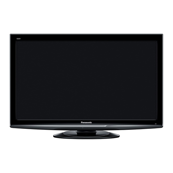
Panasonic VIERA TX-L37S10B Service Manual
Hide thumbs
Also See for VIERA TX-L37S10B:
- Brochure & specs (47 pages) ,
- Operating instructions manual (72 pages)
Table of Contents
Advertisement
Service Manual
Specifications
(Informations in brackets [ ] refers to model 32")
Power Source:
Power Consumption
Stand-by Power Consumption: 0.3W (Without monitor out recording)
Aerial Impedance:
Receiving System:
Receiving Channels:
Operating Conditions:
PC signals:
220-240V AC, 50Hz
130W [115W]
13W (With monitor out recording)
75Ω unbalanced, Coaxial Type
S10B
PAL-I
PAL-525/60 (AV only)
DVB-T (via UHF aerial input)
M.NTSC (AV only)
NTSC (AV only)
S10B
UHF E21-E68
0°C ÷ 35°C
Temperature:
Humidity: 20% ÷ 80% RH (non condensing)
VGA, SVGA, XGA, SXGA(compressed)
Horizontal scanning frequency
Vertical scanning frequency
Colour LCD Television
GLP24 Chassis
S10E,S10L,LFS10
PAL-I/H, B/G, D/K
SECAM B/G, D/K, L/L'
PAL-525/60 (AV only)
DVB-T (via VHF/UHF aerial input)
DVB-C (Digital cable services)
M.NTSC (AV only)
NTSC (AV only)
S10E,S10L,LFS10
VHF E2-E12
VHF A-H (ITALY)
VHF R3-R5
UHF E21-E69
CATV S1-S10 (M1-M10)
CATV S21-S41 (Hyperband)
31 – 69 kHz
59 – 86 Hz
ORDER No. PCZ0903045CE
TX-L32S10B
TX-L32S10E
TX-L32S10L
TX-L37S10B
TX-L37S10E
TX-L37S10L
TX-LF32S10
TX-LF37S10
VHF H1-H2 (ITALY)
VHF R1-R2
VHF R6-R12
CATV (S01-S05)
CATV S11-S20 (U1-U10)
VHF A-J (IRELAND)
© Panasonic Corporation 2008.
Unauthorized copying and
distribution is a violation of law.
Advertisement
Table of Contents

Summarization of Contents
Safety Precautions
Touch-Current Check
Procedure for verifying touch currents to ensure user safety.
About Lead Free Solder
Suggested Lead Free Solder
Recommendations for suitable lead-free solder types for repairs.
Applicable Signals
PC Signal Compatibility (D-sub 15P)
Specifies PC signal timings compatible with the D-sub 15-pin input.
PC Signal Compatibility (HDMI)
Specifies PC signal timings compatible with the HDMI input.
Service Hints
How to Remove the Back Cover
Instructions for removing the rear panel of the unit.
How to Remove the Pedestal Assembly
Instructions for detaching the TV stand from the unit.
Chassis Board Layout
Location of Lead Wiring
Identifies the location of required wires for service.
Setting Inspection
Voltage Confirmation
Lists test points and expected voltages for verification.
Service Mode Function
How to Enter Service Mode
Instructions on how to access the service menu using the remote.
Service Mode Operations
Service Mode Key Commands
Explains the function of remote control buttons within the service menu.
Adjustment Method
Sub-Contrast and White Balance Adjustment
Details on adjusting sub-contrast and white balance using specific equipment.
White Balance Adjustment Details
Specifies procedures and parameters for white balance calibration.
Replacement Parts List
Important Safety Notice for Parts Replacement
Critical safety advice for replacing specific components.
Retention Time Limited (RTL) Parts
Information regarding parts with limited availability periods.
Common Parts and Component Lists
Comprehensive lists of common parts, ICs, fuses, diodes, etc.
Schematic Diagrams
Safety Notice for Schematic Diagrams
Important safety precautions when working with schematic diagrams.
Schematic Diagram Conventions
Explains conventions for resistors, capacitors, coils, test points, etc.
Schematic Diagram Usage Remarks
Important remarks regarding safe handling and connection of instruments.


Need help?
Do you have a question about the VIERA TX-L37S10B and is the answer not in the manual?
Questions and answers