Table of Contents
Advertisement
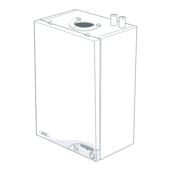
Advanced High Efficiency Boilers
H12, H16, H19, H22
(V3 Flue System)
Wall mounted, balanced flue, fanned gas boiler
For details of document amendments, refer to page 3
October 2007
UIN 203323 A02
Installation & Servicing Instructions
See reverse for evo HE Users Guide
Manufactured exclusively for Wolseley Centers Ltd. by Ideal Boilers
Advertisement
Table of Contents

Related Manuals for Evo HE H19


Summary of Contents for Evo HE H19
- Page 1 Wall mounted, balanced flue, fanned gas boiler For details of document amendments, refer to page 3 October 2007 UIN 203323 A02 Installation & Servicing Instructions See reverse for evo HE Users Guide Manufactured exclusively for Wolseley Centers Ltd. by Ideal Boilers...
- Page 2 HE H - Installation & Servicing...
- Page 3 Page 49 - Short Parts List Parts List updated. • USERS GUIDE - Page 2 Addition of two bullets into important notes. Wolseley Centers Ltd. reserve the right to vary specification without notice evo HE H - Installation & Servicing...
-
Page 4: Sedbuk No
GENERAL Table 1 - Boiler Data Boiler Size H12, H16, H19, H22 Gas supply type and connection 2H-G20-20 mbar Rc " BSP Female Injector size Stereomatic 5.6mm dia. (HE 12 5.8mm dia). Flow connection 22mm copper Return connection 22mm copper Flue terminal diameter mm (in.) -
Page 5: Table Of Contents
For all boilers: complete, sign & hand over to customer For assistance see Technical Helpline on the back page NOTE TO THE INSTALLER: COMPLETE THE BENCHMARK COMMISSIONING CHECKLIST AND LEAVE THESE INSTRUCTIONS WITH APPLIANCE evo HE H - Installation & Servicing... -
Page 6: Boiler Clearances
") from the cupboard door but 450mm (17 ") ventilated enclosed cupboard. However, 100mm must be overall clearance is still required, with the cupboard door available for servicing. open, to allow for servicing. evo HE H - Installation & Servicing... -
Page 7: Gas Safety Regulations
Powered Vertical Flue Kit 5m primary and 17m secondary is a typical maximum length. For alternative maximum lengths The evo HE range of boilers are a fully automatically controlled, refer to Powered Vertical Instructions. wall mounted, low water content, balanced flue, fanned, High Level Flue Outlet Kits condensing gas boiler. -
Page 8: Gas Supply
Tonbridge. kent TN9 1TB www.ffc.ukco.com N.B. The principle of the 1:1 gas valve ensures that the evo HE 5. The flue assembly shall be so placed or shielded as to H range is able to deliver it’s full output at inlet pressures prevent ignition or damage to any part of any building. -
Page 9: Air Supply
IMPORTANT. Any external runs must be insulated. 11.7 14.7 17.6 20.5 23.4 The drain outlet on the boiler is standard 21.5mm ( ”) Boiler Output (kW) overflow pipe. evo HE H - Installation & Servicing... -
Page 10: Controls
Check that with only the domestic hot water loop in circuit a differential temperature of 20 C across the boiler is not exceeded. 4. Adjust room and cylinder thermostats and programmer to NORMAL settings. evo HE H - Installation & Servicing... - Page 11 The valve expansion vessel. should have the following features: evo HE H - Installation & Servicing...
- Page 12 Sizing procedure for expansion vessels: The volume of the expansion vessel (litres) fitted to a sealed system shall not be less than that given by the table on the following page, multiplied by a factor of 0.8 (for flow temperatures of less than 83 evo HE H - Installation & Servicing...
-
Page 13: Inhibitor
0.134 0.237 0.113 0.20 WATER TREATMENT The evo HE boiler range has an ALUMINIUM alloy heat exchanger The application of any other treatment to this product may render the guarantee of IMPORTANT. Wolseley Centers Ltd. invalid. Wolseley Centers Ltd. recommend water treatment in accordance with the Benchmark Guidance Notes on Water Treatment in Central Heating systems. - Page 14 20. Fan bracket assy. Insulation. 44. Wall mounting plate. Flue sensing nipple. 21. Orifice plate. 13. Heat exchanger. 53. Turret gasket kit. Return pipe. 22. Flue thermistor. 94. Ignition lead. 14. Injector & housing. Flow pipe. evo HE H - Installation & Servicing...
- Page 15 5. When ready for installation lift off the outer sleeve. 6. Remove the top protection packing. 7. Remove the two packaging ends. 8. Remove the hardware pack from under the pipes nm7818 and keep in a safe place. evo HE H - Installation & Servicing...
- Page 16 Up to 4395 mm Pack D - 4 off Up to 5345 mm Up to 5345 mm Pack D - 5 off Up to 6000 mm Up to 6000 mm Pack D - 6 off evo HE H - Installation & Servicing...
- Page 17 (choosing one from each group). The position of the flue duct hole (see diagram below, and template). Note. Mark the centre of the hole as well as the circumference 5. Remove the template from the wall. evo HE H - Installation & Servicing...
-
Page 18: Preparing The Wall
Measurement to be taking care not to pierce plastic inner flue. taken from this point 5. Fix to length using self tappers provided. nm8945 6. Seal outer air duct using the tape provided. evo HE H - Installation & Servicing... - Page 19 525mm this can be taken up by the adjustment in the telescopic flue. 5. If the remainder Y is 525mm - 950mm it will be necessary to cut a ‘D’ pack to 400mm. esp8940 evo HE H - Installation & Servicing...
-
Page 20: Condensate Drain
* If drain termination is to soil below grating but stack, a 75mm trap will be above water level required cla7772 75mm trap Ground Level DRAIN continued ..evo HE H - Installation & Servicing... - Page 21 Soak away cla7774 Ground Level minimum 500mm 5. TERMINATION TO DRAIN / GULLEY External wall Open end of pipe BOILER direct into gulley below grating but above water level cla7775 Ground Level DRAIN evo HE H - Installation & Servicing...
-
Page 22: Mounting The Boiler
2 studs and fixing NB. The space bracket will utilise one fixing hole only whilst it in the middle with the single M5 x 10mm pozi-hex screw used in conjunction with the stand-off option. provided. evo HE H - Installation & Servicing... - Page 23 29 ROOF FLUE KIT CONTENTS / OPTIONS Flue Terminal Flue Seal Collar - Flat Roof Vertical connector elbow elbow Flue Flue Seal Collar - Tile Roof duct support Roof Flue Extentsion Duct evo HE H - Installation & Servicing...
-
Page 24: Flue Terminal Position
690mm Fixed Terminal Position Minimum Dimension Directly below an opening, air brick, windows, etc. 300 mm Below plastic / painted gutters 300 mm Painted surface 300 mm Below eaves or balcony 500 mm evo HE H - Installation & Servicing... - Page 25 INSTALLATION 31 FLUE ARRANGEMENT Note. The equivalent flue length resistance of the elbow kits are: elbow kit = 1m elbow kit = 0.6m evo HE H - Installation & Servicing...
-
Page 26: Assembling The Roof Flue Kit
5. Finally ensure the roof flashing plate is correctly sealed to the roof. evo HE H - Installation & Servicing... -
Page 27: Electrical Connections
Wiring external to the boiler MUST be in accordance with the system controls. The means of isolation must be current I.E.E. (BS.7671) Wiring Regulations and any local accessible to the user after installation. regulations. evo HE H - Installation & Servicing... -
Page 28: Controls
Ecl 1542 Incoming mains wiring detail Remove link when connecting external programmer. Mains Connector Socket (supplied in hardware pack) (fixed to boiler) evo HE H - Installation & Servicing... -
Page 29: Flow Wiring Diagram
- violet DC Gas valve w - white y - yellow Spark generator y/g - yellow/green Ignition electrode Flue thermistor CH return thermistor (not fitted) User PCB nm 7201 Control thermistor evo HE H - Installation & Servicing... -
Page 30: External Electrical Controls
WARNING. Whilst effecting the required gas soundness test and purging air from the gas installation, open all windows and doors, extinguish naked lights and DO NOT SMOKE. evo HE H - Installation & Servicing... -
Page 31: Initial Lighting
N.B. The principle of the 1:1 gas valve ensures that the B Thermostat knob. J Casing pressure test point. evo HE H range is able to deliver it’s full output at inlet D 'Burner On' neon. K Overheat thermostat. pressures down to 14mb. However if dynamic E Reset button. -
Page 32: Handing Over
Emphasise that if a fault is indicated the boiler should be person. turned off and a CORGI registered installer consulted. In IE contact a competent person. evo HE H - Installation & Servicing... -
Page 33: Benchmark Commissioning Checklist
3. To remove the bottom panel remove the 2 screws. 4. Pull the RH side of the panel down. Slide it to the right and withdraw. evo HE H - Installation & Servicing... -
Page 34: Burner Removal And Cleaning
4. Inspect the sealing gasket around the Probes burner and combustion chamber insulation for any signs of damage. Replace as necessary. Note. Take care not to disturb the ionisation probes at the front and rear of the combustion chamber. evo HE H - Installation & Servicing... -
Page 35: Cleaning The Heat Exchanger
8. Refit the boiler front and bottom panels. 4. Refit the burner. 9. Turn on the gas supply at the gas service cock. 5. Refit the fan / venturi assembly. 10. Reconnect the electrical supply. evo HE H - Installation & Servicing... -
Page 36: Replacement Of Components
6. Reassemble the boiler in reverse order. 7. Check the operation of the boiler. Refer to Frame 52. nm8753 evo HE H - Installation & Servicing... -
Page 37: Fan Replacement
7. Reassemble in reverse order. Probes 8. Check the operation of the boiler. Refer to Frame 52. Note. Take care not to disturb the ionisation probes at the front and rear of the combustion chamber. evo HE H - Installation & Servicing... -
Page 38: Ignition Electrode Replacement
Check dimension as shown. 7. Reassemble in reverse order and check that no damage to the combustion chamber insulation has occurred during the electrode replacement. 8. Check operation of the boiler. Refer to Frame 52. evo HE H - Installation & Servicing... -
Page 39: Spark Generator Replacement
8. Transfer the mounting bracket and gas inlet pipe to the new gas control valve. 9. Fit new gas control valve, ensuring that any seals showing damage or deterioration are replaced. Ecl 2343 evo HE H - Installation & Servicing... -
Page 40: Control Box Replacement
(refer to Frame 38) and the key on the switch is correctly aligned with the slot in the plastic moulding. 6. Reassemble in reverse order. 7. Check operation of the boiler. Refer to Frame 52. evo HE H - Installation & Servicing... -
Page 41: Overheat Thermostat Replacement
5. Withdraw the thermistor. 6. Unplug the inline electrical connector. 7. Fit the new thermistor, using the gasket supplied. 8. Reassemble in reverse order. 9. Check operation of the boiler. Refer to Frame 52. nm8747 evo HE H - Installation & Servicing... -
Page 42: Combustion Chamber Insulation Replacement
17. Check operation of the boiler. Refer to Frame 52. Fit insulation in the following order: Rear. LH Side Rear Left Hand Side. Front. Right Hand Side. Front RH Side Combustion chamber nm8748 evo HE H - Installation & Servicing... -
Page 43: Heat Exchanger Replacement
13. Unscrew the M5 x 10 screw retaining the top manifold flue casing. 14. Remove the top half of the flue manifold from the appliance. 15. Undo the 4 M5 x 10 screws scuring the bottom flue manifold casting. nm8749 evo HE H - Installation & Servicing... -
Page 44: Boiler Sealing Panel Seal Replacement
7. Reassemble in reverse order, ensuring that the new trap is full of water. 4. Undo the plastic union nut on the condensate 'S' trap outlet. 8. Check operation of the boiler. Refer to Frame 52. nm7822 evo HE H - Installation & Servicing... -
Page 45: Fault Finding
ALTERNATING 'H' '4' GO TO FRAME 76 GO TO FRAME 77 ALTERNATING 'H' 'n' ALTERNATING 'H' 'E' GO TO FRAME 71 GO TO FRAME 76 ALTERNATING 'H9' ALTERNATING 'L9' GO TO FRAME 76 evo HE H - Installation & Servicing... - Page 46 Press and hold reset button for 2 seconds. Does boiler operate Internal fault within the PCB correctly? Turn boiler off and wait for 5 seconds.Turn boiler on. Does boiler operate correctly? Replace PCB evo HE H - Installation & Servicing...
- Page 47 At 85 expect 1,000 - 1,100 Ohms Are the thermistor values correct ? Replace the thermistor Replace PCB Is there continuity between the PCB and the thermistor ? Check and replace wiring as necessary evo HE H - Installation & Servicing...
- Page 48 Replace thermistor Replace thermistor Inspect heat exchanger for blockage or damage in the flueways. Clean or replace as necessary 77 H..n..(PHASE REVERSAL ERROR) Check wiring to the boiler for reversed live and neutral evo HE H - Installation & Servicing...
-
Page 49: Short List Of Parts
Main switch c/w harness 173 537 Spark generator 173 538 E65-527 Gasket kit 170 938 E68-376 Seal kit - sealing panel 171 014 E68-380 Turret gasket 171 022 Ignition lead 173 510 Detection lead 173 511 evo HE H - Installation & Servicing... -
Page 50: Short List
SHORT LIST OF PARTS 78 SHORT LIST nm8077 79 BOILER CASING ASSEMBLY 1. Front casing panel with screws. 2. Sealing panel with screws. 4. Bottom casing panel with screws. evo HE H - Installation & Servicing... -
Page 51: Burner Assembly
Controls assy with screws. Controls hinge bracket. User controls (without item 38). PCB (primary controls). User control housing Mains switch. Jumper link. 81 BURNER ASSEMBLY 11. Burner assembly with screws and gasket. Ecl 1598 evo HE H - Installation & Servicing... - Page 52 NOTES evo HE H - Installation & Servicing...
-
Page 53: Installer Notification Guidelines
IT IS A CONDITION OF THE MANUFACTURERS WARRANTY THAT THE BENCHMARK CORGI will record the data and COMMISSIONING CHECKLIST IS will send a certificate of compliance to the property FULLY COMPLETED AND LEFT WITH THE APPLIANCE evo HE H - Installation & Servicing... -
Page 54: Time And Temperature Control To Heating
BENCHMARK No. GAS BOILER COMMISSIONING CHECKLIST C O L L E C T I V E M A R K BOILER SERIAL No. NOTIFICATION No. CONTROLS To comply with the Building Regulations, each section must have a tick in one or other of the boxes TIME &... -
Page 55: Service Interval Record
SERVICE INTERVAL RECORD It is recommended that your heating system is serviced regularly and that you complete the appropriate Service Interval Record Below. Service Provider. Before completing the appropriate Service Interval Record below, please ensure you have carried out the service as described in the boiler manufacturer's instructions. - Page 56 The code of practice for the installation, commissioning & servicing of central heating systems Wolseley Installer/Technical Helpline: 0870 8498057...
Need help?
Do you have a question about the H19 and is the answer not in the manual?
Questions and answers