Advertisement
Safety • Assembly • Operation • Adjustments • Maintenance • Troubleshooting • Parts Lists • Warranty
OPERATOR'S MANUAL
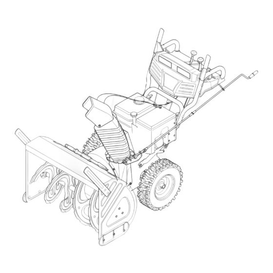
28", 30", 33" & 45"Two-Stage Snowthrowers
IMPORTANT:
READ SAFETY RULES AND INSTRUCTIONS
CAREFULLY BEFORE OPERATING EQUIPMENT.
LES DISTRIBUTIONS RVI LIMITÉE, 2955, JEAN-BAPTISTE DESCHAMPS, LACHINE, QUEBEC H8T 1C5
MTD LLC, P.O. BOX 361131 CLEVELAND, OHIO 44136-0019
769-05178
PRINTED IN U.S.A.
6/17/09
Advertisement
Table of Contents

Related Manuals for Columbia 30"


Summary of Contents for Columbia 30"
- Page 1 Safety • Assembly • Operation • Adjustments • Maintenance • Troubleshooting • Parts Lists • Warranty OPERATOR’S MANUAL 28”, 30”, 33” & 45”Two-Stage Snowthrowers IMPORTANT: READ SAFETY RULES AND INSTRUCTIONS CAREFULLY BEFORE OPERATING EQUIPMENT. LES DISTRIBUTIONS RVI LIMITÉE, 2955, JEAN-BAPTISTE DESCHAMPS, LACHINE, QUEBEC H8T 1C5 MTD LLC, P.O.
-
Page 2: Table Of Contents
This Operator’s Manual is an important part of your new snow thrower. It will help you assemble, prepare and maintain the unit for best performance. Please read and understand what it says. Table of Contents Safety Symbols........... 3 Maintaining Your Snow Thrower ...... 16 Safe Operation Practices ........ -
Page 3: Safety Symbols
This page depicts and describes safety symbols that may appear on this product. Read, understand, and follow all instructions on the machine before attempting to assemble and operate. Symbol Description Safety READ THE OPERATOR’S MANUAL(S) Read, understand, and follow all instructions in the manual(s) before Symbols attempting to assemble and operate. -
Page 4: Safe Operation Practices
WARNING: Engine Exhaust, some of its constituents, and certain vehicle compo- nents contain or emit chemicals known to State of California to cause cancer and birth defects or other reproductive harm. DANGER: This machine was built to be operated according to the safe operation practices in this manual. - Page 5 8. Exercise extreme caution when operating on or crossing gravel 3. Check bolts and screws for proper tightness at frequent surfaces. Stay alert for hidden hazards or traffic. intervals to keep the machine in safe working condition. Also, visually inspect machine for any damage. 9.
-
Page 6: Setting Up Your Snowthrower
IMPORTANT: The snow thrower is shipped with oil and WITHOUT GASOLINE. After assembly, refer to separate engine manual for proper fuel and engine oil recom- mendations. Loose Parts Setting Up • The augers are secured to the auger shaft with shear Your pins and bow tie cotter pins. - Page 7 Attaching the Chute Assembly • Cut and remove the cable tie holding the chute assembly to the spiral end of the chute crank. • Remove locknuts and screws securing one of the flange keepers to the chute assembly. See Figure 3-4. Setting Up Your Snowthrower...
- Page 8 • Normally the cable ties holding the steering cables against the handle are loosely installed on each side of the lower handle at the factory. Pull the cable ties tight to secure. Cut the excess from the ends of cable ties.
- Page 9 • Move the shift lever into the fast reverse (R2) position and repeat the previous two steps. If you experienced resistance rolling the unit, either when repositioning the shift lever from 6 to R2 or when attempting to move the machine with the drive control released, adjust the drive control immediately.
-
Page 10: Operating Your Snowthrower
Know Your Snow Thrower Drive Control Shift Lever Two-Way Chute Control™ Operating (optional) Auger Control Your Wheel Steering Control Snowthrower Chute Directional Chute Control Assembly Drift Cutters (optional) Engine Controls Clean-Out Tool Oil Filler Cap/ Dipstick Ignition Key Primer Fuel Fill Cap Starter Handle Electric Switch Box* WARNING... - Page 11 Chute Directional Control AUGER The chute directional control can be turned clockwise or CONTROL counterclockwise to change the direction in which snow is thrown. CHUTE DIRECTIONAL CONTROL Operating Your DISCHARGE DISCHARGE LEFT RIGHT CHUTE TILT Snowthrower Drive Control / Auger Control Lock DOWN The drive control is located on the right handle.
- Page 12 Gas & Oil Fill-Up Engines with Electric Starters WARNING: The electric starter is Service the engine with gasoline and oil as instructed in equipped with a grounded three-wire the separate engine manual packed with your unit. Read power cord and plug, and is designed instructions carefully.
- Page 13 Stopping the Engine To Engage Augers 1. To engage augers and start snow throwing, squeeze WARNING: To avoid unsupervised en- the left hand auger control against the left handle. gine operation, never leave the engine Release to stop augers. unattended while running. Turn the engine off after use and remove ignition 2.
-
Page 14: Makingadjustments
Making Adjustments Figure 5-1 WARNING Shift Rod If the full range of speeds (forward and reverse) cannot Figure 5-2 be achieved, refer to Figure 5-1 and adjust the shift rod as follows: Read, understand, 1. Looking underneath the handle panel, note which and follow all instruc- of the three holes in the shift lever the ferrule is tions and warnings... - Page 15 Skid Shoes The space between the shave plate and the ground can be adjusted by raising or lowering the skid shoes. For close snow removal, as when using on a smooth concrete or asphalt driveway, place the skid shoes in the low position.
-
Page 16: Maintaining Your Snowthrower
Lubrication Drive and Shifting Mechanism At least once a season or after every 25 hours of opera- Gear tion, remove rear cover. Lubricate any chains, sprockets, (Hex) gears, bearings, shafts, and the shifting mechanism at Shaft Friction least once a season. Use engine oil or a spray lubricant. Wheel Maintaining Refer to Figure 6-1. - Page 17 3. a. Loosen the bolt shown in Figure 6-5 securing the belt keeper bracket and remove the other bolt. b. Push the belt keeper and bracket up off the engine pulley. See Figure 6-5. Auger Belt 4. Remove the clip and flat washer from the ferrule in Maintaining order to disconnect the auger idler rod from the brake bracket assembly.
-
Page 18: Drive Belt
8. Place a block of wood underneath the auger housing as shown in Figure 6-9 and separate auger housing from the frame by tilting the housing forward and pulling up the handles. 9. Block the impeller with a piece of wood to prevent if from spinning and use a 1/2”... - Page 19 4. Install the new belt on the pulleys in the reverse order and re-tension with the idler pulley. Shift Arm 5. Reassemble your unit by performing the Friction previous steps in the opposite order. Wheel Assembly Changing Friction Wheel Remove hex Maintaining Slide Rubber...
-
Page 20: Off-Season Storage
If unit is to be stored over 30 days, prepare for storage as instructed in the separate engine manual packed with your snowthrower. • Clean snowthrower thoroughly. • Lubricate as instructed in the Maintenance section of this manual. Off-Season • Refer to engine manual for correct engine storage instructions. -
Page 21: Trouble Shooting
Problem Cause Remedy 1. Choke not in CHOKE position. 1. Move choke to CHOKE position. Engine fails to start 2. Spark plug wire disconnected. 2. Connect wire to spark plug. 3. Fuel tank empty or stale fuel. 3. Fill tank with clean, fresh gasoline. 4. -
Page 22: Warranty
THREE YEAR LIMITED WARRANTY The limited warranty set forth below is given by MTD Products Limited with respect to new merchandise purchased and used in Canada and/or its territories and possessions (either entity respectively, “MTD”). MTD warrants this product (excluding its normal wear parts as described below) against defects in material and workman- ship for a period of three (3) years commencing on the date of original purchase and will, at its option, repair or replace, free of charge, any part found to be defective in materials or workmanship. - Page 23 For three (3) years-120 hrs. whichever come first, from the date of original purchase of COLUMBIA products, COLUMBIA will either repair or replace, at its option, free of charge, F.O.B. factory or authorized service firm, any part found to be defective in material and workmanship. All transportation charges on parts submitted for Warranty replacement under this warranty must be paid by the purchaser unless return is requested by COLUMBIA.
Need help?
Do you have a question about the 30" and is the answer not in the manual?
Questions and answers