Table of Contents
Advertisement
Quick Links
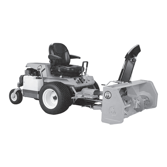
Two-Stage Snow Blowers
Operator's Manual
Safety, Assembly, Operating, and Maintenance Instructions
42" Model
P/N: 6670-1
S/N: 21210627 and up
Please Read and Save These Instructions
For Safety, Read All Safety and Operation
Instructions Prior to Operating Machine
50" Model
P/N: 6670-20
S/N: 21210627 and up
Effective Date: 08.01.14
Advertisement
Table of Contents

Related Manuals for Walker 50"


Summary of Contents for Walker 50"
- Page 1 Two-Stage Snow Blowers Operator’s Manual Safety, Assembly, Operating, and Maintenance Instructions 42” Model 50” Model P/N: 6670-1 P/N: 6670-20 S/N: 21210627 and up S/N: 21210627 and up Please Read and Save These Instructions For Safety, Read All Safety and Operation Instructions Prior to Operating Machine Effective Date: 08.01.14...
- Page 2 Walker Mfg. Co. is continually striving to improve the design and performance of its products. We reserve the right to make changes in specifications and design without thereby incurring any obligation relative to previously manufactured products.
-
Page 3: Table Of Contents
TABLE OF CONTENT INTRODUCTION – TO THE PURCHASER ....................3 SAFETY PRECAUTIONS ........................... 4 Before Operation ..........................4 Notice ..............................5 The Snowblower ..........................5 Before Operation ........................ 5 Snowblower Operation ....................... 6 The Tractor ............................7 General Information ......................7 Operating the Tractor ...................... - Page 4 TABLE OF CONTENT MAINTENANCE ............................19 Maintenance ............................ 19 Drive Chain Adjustment ....................19 Reduction Sprocket Removal ..................19 Shear Bolts ........................19 Lubrication ............................20 Auger Sections ........................ 20 Worm Gearbox ........................ 20 Drive Chain ........................20 Chain ..........................20 PARTS ..............................
-
Page 5: Introduction - To The Purchaser
INTRODUCTION O THE URCHASER Illustrations The illustrations may not necessarily reproduce All products are designed to give safe, the full detail and the exact shape of the parts or dependable service if they are operated and depict the actual models, but are intended for maintained according to instructions. -
Page 6: Safety Precautions
SAFETY PRECAUTIONS SAFETY FIRST This symbol, the industry's "Safety Alert Symbol", is used throughout this manual and on labels on the machine itself to warn of the possibility of personal injury. Read these instructions carefully. It is essential that you read the instructions and safety regulations before you attempt to assemble or use this unit. -
Page 7: Notice
SAFETY PRECAUTIONS - continued OTICE A safe operator is the best assurance against accidents. All operators, no matter how experienced they may be, should read this operator's manual and all other related manuals before attempting to operate an equipment. Please read the following section and pay particular attention to all safety recommendations contained in this manual and those labeled on the equipment and on the tractor. -
Page 8: Snowblower Operation
SAFETY PRECAUTIONS - continued NOWBLOWER PERATION 1. In case of a belt-driven equipment, make sure 10. If snowblower starts vibrate drive belt is routed properly before operation. abnormally, stop the engine immediately and check for cause. Excessive vibration is 2. Before leaving the tractor unattended, take all generally a sign of trouble. -
Page 9: The Tractor
SAFETY PRECAUTIONS - continued RACTOR 12. Fill fuel tank outdoors with extreme care. General Information Never fill fuel tank indoors. Replace fuel cap securely and wipe up spilled fuel. 1. Read the operator's manual carefully before using tractor. Lack of operating knowledge 13. -
Page 10: Maintenance
SAFETY PRECAUTIONS - continued AINTENANCE RANSPORT 1. If the tractor/equipment is to be driven on ALWAYS USE GENUINE PARTS WHEN public roads, it must be equipped with an REPLACEMENT PARTS ARE REQUIRED SMV (Slow Moving Vehicle) sign. Check 1. Park the tractor/snowblower on level ground, local traffic codes that may apply to unit place the transmission in neutral, set the usage on public roads and highways in your... -
Page 11: Decals
DECALS Replace immediately if damaged 657346 657761 660988 657762 2500938 2500937 657804 655683 657763 OM 0182SB-A... -
Page 12: Assembly
ASSEMBLY – T ITCH NSTALLATION RACTOR SIDE Before installing this hitch make sure engine is off and parking brake is set. Attaching Quick Hitch to Tractor Figure 2 Figure 2 1. Lightly grease the deck support arm shaft (fig.1, item 1) on the tractor. 2. -
Page 13: Wiring
ASSEMBLY 3. Figure 5: Drill five 13/64” (5 mm) dia. holes 7. Connect the harness red wire to the free in the tractor: two in the forward speed connector of the PTO clutch switch red control arm and three in the body as. wire. -
Page 14: Snowblower Assembly
ASSEMBLY NOWBLOWER SSEMBLY The snowblower is assembled at the factory, however snowblower kits must be assembled. Use the present manual and lay out all parts for assembly. Separate bolts and nuts into various sizes. After assembly, torque all the bolts according to the Torque Specification Table enclosed at the end of the manual. -
Page 15: Attaching Blower To Tractor
ASSEMBLY Attaching Blower to Tractor (Figures 10-11-12-13) 1. Figure 10: Remove the paint from inside the drive shaft yoke and install a 1/4" x 1/4" x 1 1/4" key (not included) in the reduction shaft keyway. 2. Figure 10: Slide the drive shaft yoke (item1) over the reduction shaft. -
Page 16: Removing Snowblower From Tractor
ASSEMBLY 6. Figure 12: Insert the male quick hitch section (item 1) into the female hitch Figure 12 (item 2) and lock in place by moving lever (item 3) to lock position (fully forward), and secure latch with linchpin. 7. Grease the drive shaft sliding surfaces and slide the male shaft inside the female tube. -
Page 17: Installation Of Electric Chute Rotation Kit 475 (Option)
ASSEMBLY Installation of Electric Chute Rotation Kit 9475 (Option) (Figure 14 and Electrical diagram) 1. Insert 1 11/16" (43 mm) plastic bushing 10. Connect one end of a 5" (127 mm) wire to (item 1) in rotation bracket (item 2). "A"... -
Page 18: Installation Of Electric Deflector Kit 9370 (Option)
ASSEMBLY Installation of Electric Deflector Kit 9370 (Option) (Figure 15 and Electrical Diagram) 1. Remove manual adjustment knob and bolts 8. Connect one end of the 5” (127 mm) wire to from sides of deflector and replace them a terminal and other end to "d" terminal on with two 5/16”... -
Page 19: Operation
OPERATION ENERAL REPARATION WARNING : To ensure safety, make sure 1. Read this Operator's Manual carefully. Be tractor engine and snowblower come to a thoroughly familiar with the controls and complete stop and tractor PTO is disengaged proper use of the equipment. Know how to BEFORE making any adjustments. -
Page 20: Snow Removal Method
OPERATION EMOVAL METHODS When removing snow, do not use the snowblower as a dozer blade to push snow. Let the snowblower work its way through deep drifts. If the speed of your tractor is too fast, the snowblower may become overloaded and clog. -
Page 21: Maintenance
MAINTENANCE AINTENANCE Shear Bolts 1. Always use a special grade 5 shear bolt ALWAYS GENUINE PARTS WHEN (656053) on fan (item 1) and grade 5 two REPLACEMENT PARTS ARE REQUIRED grooved shear bolts, silver plated (657295) on the auger (item 2) as shown on decal (657346) . -
Page 22: Lubrication
MAINTENANCE UBRICATION Use a good grease gun and lubricate as follows: DESCRIPTION INTERVAL LUBRICATION REQUIRED 8 hours Grease each universal joint Driveline Separate the sliding parts and cover each one of 24 hours them with grease 4 hours Driving chain Lubricate with chain saw lubricant and after each operation 24 hours of operation... -
Page 23: Parts
PARTS NTRODUCTION All parts are illustrated in "exploded views" which show the individual parts in their normal relationship to each other. Reference nums are used in the illustrations. These nums correspond to those in the "Reference Num" (REF) column, and are followed by the description and quantity required. O/L - "Obtain Locally"... -
Page 24: Male Quick Hitch Assembly - 6625
PARTS - 6625 UICK ITCH SSEMBLY ESCRIPTION UMBER Male quick hitch 660980 Quick hitch latch 657382 Hex. bolt 3/8” NC x 1 1/2” 0100040 Nylon lock nut 3/8” NC 1000006 Pin 1/4” dia x 1 5/8” 657384 Cotter pin 5/64" dia. x 1" 1500032 Spring plate 657383... -
Page 25: Male Quick Hitch System
PARTS UICK ITCH YSTEM ESCRIPTION UMBER Adaptor 6620-27 5830-3 Grease fitting 45. Hex. bolt 3/4” F212 Jam nut 3/4” F213 Clevis pin 6621-1 Actuator motor 6621 Pivot shaft 6620-17 Hitch 6620-24 Keps nut 10-24 F002 Keps nut 1/4-20 F005 Bolt 1/4-20 x 1/2" F036 Decal 6620-29... -
Page 26: Snowblower Assembly 6670-1 (42") & 6671-20 (50")
PARTS – 6670-1 & 6671-20 NOWBLOWER SSEMBLY OM 0182SB-A... - Page 27 PARTS – 6670-1 & 6671-20 NOWBLOWERS SSEMBLY UMBER 6670-1 6671-20 ESCRIPTION Frame 669690 669692 Gearbox (cw) 4500035 4500035 Seal kit 665775 665775 Fan assembly including bushings 4300055 657327 657327 Bushing (Oilite) 4300055 4300055 Skid shoes 669674 669674 Carriage bolt 5/16" NC x 1" 0300003 0300003 Key woodruff...
-
Page 28: Reduction Box Assembly
PARTS EDUCTION SSEMBLY ESCRIPTION Reduction box ass'y inc. bearing & sprocket 657353 Reduction box 657355 Drive shaft with sprocket (H40C11) 657250 Bearing 1" bore with set screw 665494 Bearing flange 656589 Carriage bolt 5/16"NC x 5/8" 0300001 Lockwasher 5/16", PTD 1200003 Hex. -
Page 29: Standard Chute With Deflector
PARTS HUTE WITH EFLECTOR ESCRIPTION Chute ass'y ccw, w/ knobs & decals 667384 Knob 5/16" NC (nut included) 657309 Flat washer nylon 11/32" dia. hole 658467 Carriage bolt 5/16" NC x 1" PTD 0300003 Flat washer nylon 7/16" dia. hole 658468 Hand guard 657308... -
Page 30: Manual Chute Rotation System
PARTS ANUAL HUTE OTATION YSTEM ESCRIPTION UMBER Plastic bushing 1 5/16" (33 mm) 657335 Rotation worm (cw) 657733 Rotation support 657493 Rotation handle 661035 Plastic handle 656797 Hex. bolt 1/4" NC x 1" 0100004 Nylon lock nut 1/4" NC 1000003 OM 0182SB-A... -
Page 31: Female Quick Hitch
PARTS EMALE UICK ITCH UMBER 6670-1 6671-20 ESCRIPTION Quick hitch, female part 669691 669693 Hex. bolt 1/2" NC x 1 1/4" 0100069 0100069 Lockwasher 1/2" 1200006 1200006 Hex. nylon insert locknut 1/2" NC 1000011 1000011 OM 0182SB-A... -
Page 32: Female Quick Hitch Assembly 6670-1
PARTS 6670-1 EMALE UICK ITCH SSEMBLY FOR ESCRIPTION UMBER Quick hitch assembly, female part, for 6670-1 669691 Cotter pin F068 Clevis pin 6621-1 Parallel bar 6670-2 OM 0182SB-A... -
Page 33: Driveline Male Portion Assembly
PARTS 6671 RIVELINE ORTION SSEMBLY ESCRIPTION UMBER Outer shield 6671-1 Nylon bearing 6671-2 Bearing retainer 6671-3 Male shaft and yoke assembly 6671-4 OM 0182SB-A... -
Page 34: Electric Chute Rotation Kit- 9475 (Option)
PARTS – 9475 (O LECTRIC HUTE OTATION PTION ESCRIPTION UMBER Flat washer 4/4" (5/16"hole), PTD 1400002 Electric motor support CCW 664827 Worm adaptor 662459 Electric motor 662455 Rotation worm 660246 Retaining plate (not included in 9475 kit) 657333 Spacer ring 666691 Setscrew 1/4"... -
Page 35: Electric Deflector Kit- 9370 (Option)
PARTS – 9370 (O LECTRIC EFLECTOR PTION ESCRIPTION Support plate 665773 Spacer 665774 Actuator 656848 Shoulder screw 1/4" x 1 1/2" (10-24 NC) 3200010 Nylon hex. nut (10-24 NC) 1000002 Hex. Bolt 1/4" NC x 3/4" 0100003 Serrated flange nut 1/4" NC 0900058 Connector tap 656665... -
Page 36: Worm Gearbox
PARTS (4500035) EARBOX ESCRIPTION Casing kit (item 1 and 2) 4500021 Left casing ------ Right casing ------ Worm and gear kit (item 3 and 4) Not available Gear ------ Worm ------ Driving shaft 4500036 Bearing 661147 Bearing 663234 Seal kit (item 8 and 9) 665775 Seal ------... -
Page 37: Available Equipment
AVAILABLE EQUIPMENT 42" (1.07 m) & 50" (1.27 m) 36" (.91 m) ONE STAGE TWO STAGE SNOWBLOWERS SNOWBLOWER 6670-1 5600-20 6671-20 46" (1.17 m) & 60" (1.52 m) ROTARY BROOMS 6650-B DEBRIS BLOWER 46" (1.17 m) & 60" (1.52 m) BLADES 6660 6661-20... -
Page 38: Torque Specification Table
TORQUE SPECIFICATION TABLE GENERAL SPECIFICATION TABLE Use the following torques when special torques are not given NOTE:These values apply to fasteners as received from supplier, dry, or when lubricated with normal engine oil. They do not apply if special graphited or moly sidulphide greases or other extreme pressure lubricants are used. This applies to both UNF and UNC threads. BOLT HEAD IDENTIFICATION MARKS AS PER GRADE... - Page 40 WALKER MANUFACTURING CO. 5925 E. Harmony Road Fort Collins, CO 80528 Printed in Canada...
Need help?
Do you have a question about the 50" and is the answer not in the manual?
Questions and answers