Table of Contents
Advertisement
Refrigerant; HFC-134a
Refer to "HFC-134a COOLING UNIT" Service Manual for handling this refrigerant.
ENERGY LABEL ....................................................................................................................................................2
INSTALLATION ......................................................................................................................................................2
SPECIFICATIONS .................................................................................................................................................3
THE FICHE ............................................................................................................................................................ 4
DESIGNATION OF VARIOUS PARTS .................................................................................................................. 5
LIST OF ELECTRICAL PARTS ............................................................................................................................. 6
WIRING DIAGRAM ................................................................................................................................................7
FUNCTIONS ..........................................................................................................................................................9
MODIFICATION PROCEDURE OF THE DOOR OPEN SIDE ............................................................................ 12
ASSEMBLING PROCEDURES OF MAIN PARTS AND CAUTIONS .................................................................. 14
COOLING UNIT ...................................................................................................................................................20
REPLACEMENT PARTS LIST ............................................................................................................................ 22
SERVICE MANUAL
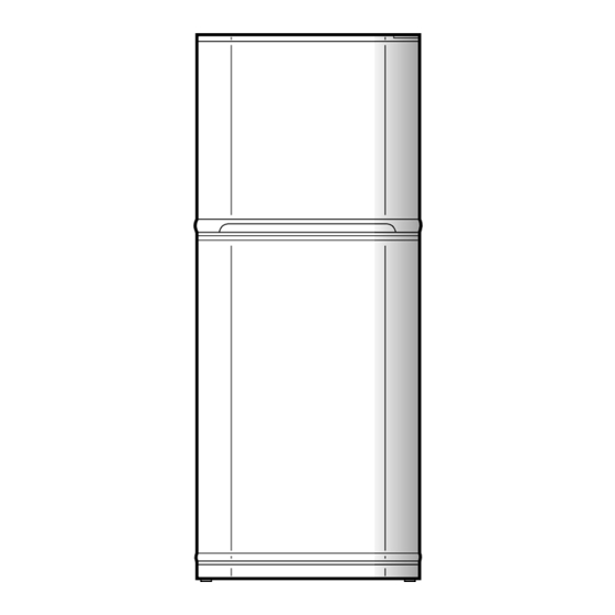
REFRIGERATOR-FREEZER
MODELS
In the interests of user-safety (Required by safety regulations in some
countries) the set should be restored to its original condition and only
parts identical to those specified should be used.
This equipment complies with
the requirements of Directives
89/336/EEC and 73/23/EEC as
amended by 93/68/EEC.
TABLE OF CONTENTS
SHARP CORPORATION
1
SJ-48H-S
SJ-51H-S
SJ-55H-S
DESTINATION ......................... E, I
SJ-48H-S
SJ-51H-S
SJ-55H-S
S0653SE55BPWI
page
Advertisement
Table of Contents

Summarization of Contents
ENERGY LABEL
Usage of "the ENERGY LABEL"
Instructions for attaching the energy label to the refrigerator for display.
INSTALLATION
Free standing type
Guidelines for adequate ventilation and placement of the refrigerator.
SPECIFICATIONS
COLOR
Specifies the available colors for the refrigerator's interior and exterior.
SOURCE, RATING AND NET WEIGHT
Details electrical ratings, input, refrigerant, and net weight.
OPTIONAL ITEM
Lists an optional item for changing the door opening side.
DESIGNATION OF VARIOUS PARTS
Figure D-1. External Description
Illustrates and labels the external parts of the refrigerator.
Figure D-2. Constructions
Shows internal construction components and their locations.
WIRING DIAGRAM
Figure W-1. Wiring Diagram
Provides a schematic of the refrigerator's electrical connections.
Figure W-2. Electric Accessories Layout
Illustrates the layout of electrical accessories within the refrigerator.
FUNCTIONS
Adjustable Temperature Control
Explains how to adjust the freezer and refrigerator temperature controls.
Temperature control of refrigerator
Details the operation of the refrigerator's damper-thermostat and temperature control.
Reference value of temperature
Provides reference temperature values for different control knob settings.
DEFROSTING
No defrosting operation is necessary
Explains why manual defrosting is not required for this model.
Where is melted ice brought
Describes the path of melted ice and the role of the evaporating pan.
Automatic defrosting function
Explains the automatic defrosting cycle with circuit diagrams.
TROUBLESHOOTING AND MAINTENANCE
Troubleshooting Defrosting Issues
Lists potential causes of defrosting problems and repair references.
Dew Prevention
Explains the system for preventing dew formation on the cabinet.
Initial Starting Inspection
Procedures for checking the cooling unit and defrost device after initial setup.
MODIFICATION PROCEDURE OF THE DOOR OPEN SIDE
Fitting Instruction
Step-by-step guide for changing the refrigerator door to open from the left.
ASSEMBLY PROCEDURES AND CAUTIONS
R-CONTROL COV. ASSEMBLY
Details the assembly of the control cover, including sealing, sensor, and fixing of components.
E.V COVER ASSEMBLY
Instructions for assembling the E.V cover, fan motor, wiring, and sealing components.
COOLING UNIT
Figure C-1. Cooling unit
Diagram illustrating the layout of the cooling unit components.
Figure C-2. Location
Shows the location of the cooling unit within the refrigerator.
Figure C-3. Cooling unit
Diagram illustrating the cooling unit components for specific models.
Figure C-4. Location
Shows the location of the cooling unit for specific models.
REPLACEMENT PARTS LIST
ELECTRIC PARTS
Lists electrical components available for replacement.
MECHANICAL PARTS
Lists mechanical components available for replacement.
DOOR PARTS
Lists replacement parts specific to the refrigerator doors.
OTHER PARTS
Lists miscellaneous parts for replacement.
ATTACHMENT PARTS
Lists accessory parts that can be attached to the refrigerator.
CYCLE PARTS
Lists parts related to the refrigeration cycle.
MISCELLANEOUS
Lists various miscellaneous items like manuals and labels.


Need help?
Do you have a question about the SJ-55H-S and is the answer not in the manual?
Questions and answers