Table of Contents
Advertisement
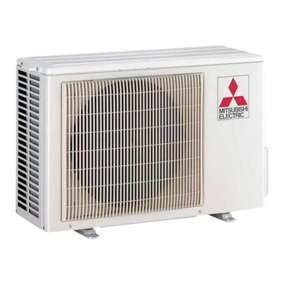
SPLIT-TYPE AIR CONDITIONERS
OUTDOOR UNIT
SERVICE MANUAL
Models
MUZ-EF25VE
MUZ-EF25VE
MUZ-EF25VEH
MUZ-EF25VEH
MUZ-EF35VE
MUZ-EF35VE
MUZ-EF25VE MUZ-EF25VEH
MUZ-EF35VE MUZ-EF35VEH
MUZ-EF42VE
NOTE:
RoHS compliant products have <G> mark on the spec name plate.
• MUZ-EF25/35/42/50VE -
have been added.
Please void OBH590 REVISED EDITION-A.
MUZ-EF35VEH
-
E1
MUZ-EF35VEH
-
E2
MUZ-EF42VE
-
E1
MUZ-EF42VE
-
E2
MUZ-EF50VE
-
E1
MUZ-EF50VE
-
E2
CONTENTS
1. TECHNICAL CHANGES ··································· 3
2. PART NAMES AND FUNCTIONS ····················· 4
3. SPECIFICATION ················································ 5
4. NOISE CRITERIA CURVES ······························ 7
5. OUTLINES AND DIMENSIONS ························ 8
6. WIRING DIAGRAM ············································ 9
7. REFRIGERANT SYSTEM DIAGRAM ··············11
8. PERFORMANCE CURVES ····························· 13
9. ACTUATOR CONTROL ··································· 27
10. SERVICE FUNCTIONS ···································· 28
11. TROUBLESHOOTING ····································· 29
12. DISASSEMBLY INSTRUCTIONS ···················· 46
PARTS CATALOG (OBB590)
and MUZ-EF25/35VEH -
E2
No. OBH590
HFC
REVISED EDITION-B
utilized
R410A
Indoor unit service manual
MSZ-EF•VE Series (OBH589)
E2
-
E1
-
E2
-
E1
-
E2
-
E1
-
E2
Advertisement
Table of Contents
Troubleshooting

Summarization of Contents
Technical Changes
New Model Introduction
Details the addition of new models and an inverter P.C. board change.
Inverter P.C. Board Change
Notes the specific change made to the inverter P.C. board.
Specification
Specifications and Rated Conditions of Main Electric Parts
Details the electrical specifications and operational conditions for main components.
Wiring Diagram
MUZ-EF25VE/MUZ-EF35VE Wiring Diagram
Provides the wiring diagram for MUZ-EF25VE and MUZ-EF35VE models.
MUZ-EF25VEH/MUZ-EF35VEH Wiring Diagram
Provides the wiring diagram for MUZ-EF25VEH and MUZ-EF35VEH models.
MUZ-EF42VE/MUZ-EF50VE Wiring Diagram
Provides the wiring diagram for MUZ-EF42VE and MUZ-EF50VE models.
Refrigerant System Diagram
MUZ-EF25VE/MUZ-EF25VEH Refrigerant Diagram
Illustrates the refrigerant system for MUZ-EF25VE and MUZ-EF25VEH.
MUZ-EF35VE/MUZ-EF35VEH/MUZ-EF42VE Refrigerant Diagram
Illustrates the refrigerant system for MUZ-EF35VE, MUZ-EF35VEH, MUZ-EF42VE.
MUZ-EF50VE Refrigerant Diagram
Illustrates the refrigerant system for MUZ-EF50VE model.
Performance Curves
Capacity and Input Curves
Presents curves showing cooling capacity and input based on operating conditions.
Capacity and Input Correction by Compressor Frequency
Shows correction factors for capacity and input based on compressor operational frequency.
How to Operate Fixed-Frequency Operation
Provides instructions for operating the unit in fixed-frequency mode.
Outdoor Low Pressure and Unit Current
Details outdoor low pressure and unit current under various conditions.
Actuator Control
Outdoor Fan Motor Control
Explains the control logic for the outdoor fan motor operation.
R.V. Coil Control
Describes the control sequence for the reversing valve (R.V.) coil.
Relation Between Main Sensor and Actuator
Maps sensors to their corresponding actuators and purposes.
Service Functions
Change in Defrost Setting
Details how to adjust the defrost finish temperature settings.
Pre-Heat Control Setting
Explains the pre-heat control function to prevent compressor start issues.
Troubleshooting
Cautions on Troubleshooting
Important safety and procedural warnings before starting troubleshooting.
Failure Mode Recall Function
Describes how to recall and interpret failure modes for diagnostics.
Troubleshooting Check Table
Lists symptoms, LED indications, abnormal points, conditions, and remedies.
Trouble Criterion of Main Parts
Provides resistance and voltage criteria for diagnosing main components.
Troubleshooting Flow
Step-by-step diagnostic flows for common issues like compressor problems.
Test Point Diagram and Voltage
Illustrates test points and voltage measurements on the inverter P.C. board.
Disassembly Instructions
MUZ-EF25VE to MUZ-EF42VE Disassembly
Step-by-step instructions for disassembling MUZ-EF25VE to MUZ-EF42VE units.
MUZ-EF50VE Disassembly
Step-by-step instructions for disassembling the MUZ-EF50VE unit.


Need help?
Do you have a question about the MUZ-EF35VE - E1 and is the answer not in the manual?
Questions and answers