Table of Contents
Advertisement
Litho U.S.A.
Table Of Contents
. . . . . . . . . . . . . . . . . . . . . . . . . . . . .
. . . . . . . . . . . . . . . . . . . . . . . . . . . . . . . . . . . . . . . . .
. . . . . . . . . . . . . . . . . . . . . . . . . . . . . .
. . . . . . . . . . . . . . . . . . . . . . . . . . .
. . . . . . . . . . . . . . . . . . . . . . . . . . . . .
. . . . . . . . . . . . . . . . . . . . . . . . . . . . . . . . . . . . . . . . . .
. . . . . . . . . . . . . . . . . . . . . . . . . . . . .
Typical LF24 Wiring Diagram
. . . . . . . . . . . . . . . . . . . . . . . . . . . . . . . . . . .
. . . . . . . . . . . . . . . . . . . . . . . . . . . . . . . . . . . . . . .
Be sure to read and understand the
installation, operation and service in-
structions in this manual.
Improper installation, adjustment, alter-
ation, service or maintenance can cause
serious injury, death or property damage.
Do not store or use gasoline or other
flammable vapors and liquids in the vi-
cinity of this or any other appliance.
Installation and service must be per-
formed by a qualified installer, service
agency or the gas supplier.
E 2011 Lennox Industries Inc.
Dallas, Texas, USA
. . . . . . . . . . . . . . . . . . . . . . . . .
. . . . . . . . . . . . . . . . . . . . . .
. . . . . . . . . . . . . . . . . . . . .
. . . . . . . . . . . . . . . . . .
. . . . . . . . . . . . . . . . . . . . . . .
RETAIN THESE INSTRUCTIONS
FOR FUTURE REFERENCE
FIRE OR EXPLOSION HAZARD.
Failure to follow safety warnings exact-
ly could result in serious injury, death,
or property damage.
INSTALLATION
INSTRUCTIONS
LF24
100,000 to 400,000 Btuh Series
UNIT HEATERS
506682−01
5/2011
Supersedes 503,523M
1
. . . . . . . . . . . . . . . . . . . . . . . . . . . . . . . . . . . . . .
2
2
3
3
3
. . . . . . . . . . . . . . . . . . . . . . . . . . . . . . . . . . . . . . . . .
3
4
5
5
10
. . . . . . . . . . . . . . . . . . . . . . . . . . . . . . . . . . . . . . . . . .
10
11
. . . . . . . . . . . . . . . . . . . . . . . . . . . . . . . . . . . . . . . . .
11
WARNING
WHAT TO DO IF YOU SMELL GAS:
S Do not try to light any appliance.
S Do not touch any electrical switch; do not use
any phone in your building.
S Leave the building immediately.
S Immediately call your gas supplier from a
neighbor's phone. Follow the gas supplier's in-
structions.
S If you cannot reach your gas supplier, call the
fire department.
. . . . . . . . . . . . . . . . . . . . . . . . . . . .
. . . . . . . . . . . . . . . . . . . . .
. . . . . . . . . . . . . . . . . . . . . . . . . . . . . . .
. . . . . . . . . . . . . . . . . . . . . . . . . . .
. . . . . . . . . . . . . . . . . . . . . . . . . .
. . . . . . . . . . . . . . . . . . . . . . . . . . . . . . .
. . . . . . . . . . . . . . . . . . . . . . . . . .
. . . . . . . . . . . . . . . . . . . . .
. . . . . . . . . . . . . . . . .
506682−01
*P506682-01*
11
13
13
13
13
15
15
15
15
15
15
16
17
Advertisement
Table of Contents

Related Manuals for Lennox LF24?300


Summary of Contents for Lennox LF24?300
-
Page 1: Table Of Contents
S If you cannot reach your gas supplier, call the Installation and service must be per- fire department. formed by a qualified installer, service agency or the gas supplier. E 2011 Lennox Industries Inc. 506682−01 *P506682-01* Dallas, Texas, USA... -
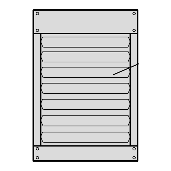
Page 2: Lf24 Unit Dimensions
(13) ELECTRICAL INLETS TOP VIEW COMBUSTION AIR INDUCER ADJUSTABLE LOUVERS DIRECT DRIVE FAN FLOW HEAT VALVE EXCHANGER END VIEW SIDE VIEW Unit LF24-100 LF24-115 31-5/16 795 32-3/16 20-3/16 11-1/2 19-1/16 11-3/4 3-1/4 7-7/8 LF24−145 LF24−175 31-5/16 795 32-3/16 23-1/8 11-1/2 22-1/16 8−1/2... -
Page 3: Optional Accessories
Optional Accessories TABLE 1 LF24−100 to LF24−230 Model No. − Stainless Steel LF24−100S LF24−115S LF24−145S LF24−175S LF24−200S Heating Performance Model No. − Aluminized Steel LF24−100A LF24−115A LF24−145A LF24−175A LF24−200A Optional Accessories − Must Be Ordered Extra 30_ − 94K94 30_ − 94K95 45_ −... -
Page 4: Csa Requirements In Usa
These unit heaters are CSA−certified for clearances to CSA Requirements in USA combustible material listed on the rating plate and table 3. Installation of gas unit heaters must conform with local Adequate clearance must be provided around the building codes or, in the absence of local codes, with the appliance and around air openings into the combustion current edition of ANSI−Z223.1, National Fuel Gas Code. -
Page 5: Additional Requirements
TABLE 4 Additional Requirements MAXIMUM MOUNTING HEIGHTS Model Number Feet (Meters) The Commonwealth of Massachusetts stipulates the LF24−100 and LF24−115 16 (4.9) following additional requirements: LF24−145, LF24−175, and 20 (6.1) LF24−200 1 − Gas furnaces shall be installed by a licensed plumber or gas fitter only. -
Page 6: Venting
2 − If the inducer is to be rotated, follow the instructions 9 − The unit heater is now ready for installation as in this section; otherwise, refer to instructions under described in the Venting section. Venting" section. Venting 3 − Before making an electrical or gas connections, remove securing screws... - Page 7 VERTICAL VENTS USING METAL VENT PIPE A single 3" (76 mm), 4" (102mm), or 5" (127 mm) elbow is equivalent to 5 feet (1.53 m) of vent pipe. A All LF24 unit heaters are listed as Category 1 appliances single 6" (152mm) elbow is equivalent to 9 feet (2.75 for vertical vent installations.
- Page 8 TABLE 6 Refer to latest editions of the ANSI Z223.1 or MAXIMUM HORIZONTAL VENT CONNECTOR AND CSA−B149 for installation compliance codes and HORIZONTAL VENT PIPE LENGTHS with local authorities with jurisdiction. LF24−100, −115, LF24−230, 6 − Vent termination must be a minimum of 4 feet −145, −175, and −250 and LF24−345...
- Page 9 NOTE − Minimum horizontal length HORIZONTAL VENTING Venting may be single−wall (26 equals 5 feet (1.53 m). This does not GSG) galvanized or equivalent include termination tee. Refer to UPWARD SLOPE stainless steel vent pipe sealed table 6 for maximum length and per these instructions, OR listed number of elbows.
- Page 10 CONDENSATE DRAIN THROUGH VENT TERMINATION DOWNWARD SLOPE ON HORIZONTAL VENT Venting may be single−wall (26 GSG) galvanized or equivalent stainless steel vent pipe sealed per these instructions, OR listed special vent for Category III appliances. SLOPE = 1/4 IN. PER FOOT RUN MAXIMUM.
-
Page 11: Electrical Connections
Connect wiring through knockout on the junction box Electrical Connections located on the side of the unit heater. Refer to heater NOTE − Local codes may supersede any of the provisions wiring diagram for connection information. Use 18 gauge outlined in this instruction. wire or larger for thermostat connections. -
Page 12: Gas Connection
The appliance must be isolated from the gas supply Gas Connection piping system by closing its individual manual gas shutoff valve during any pressure testing of the gas supply When connecting gas supply, the length of the run from system at test pressures equal to or less than 1/2 psig the meter must be considered in determining the pipe size (3.45kPa). - Page 13 6 − Wait five minutes to clear out any gas. If you then WARNING smell gas, STOP! Immediately call your gas supplier from a neighbor’s phone. Follow the Electric shock hazard. Can cause injury gas supplier’s instructions. If you do not smell or death.
-
Page 14: To Turn Off Gas To Unit
To Turn Off Gas to Unit Ignition Control LED 1 − Set thermostat to lowest level. The ignition control contains a green LED which indicates the following: 2 − Turn off all electrical power to unit if service is to be performed. - Page 15 TABLE NATURAL GAS MANIFOLD PRESSURES − in. w.g. (kPa) ALTITUDE – FEET (METERS) LF24 UNIT 0−2000 2001− 2500 2501 −3500 3501 − 4500 4501 − 5500 5501 − 6500 6501 − 7500 (0−610) (610−762) (763−1067) (1067−1372) (1372−1676) (1677−1981) (1981−2286) LF24−100** LF24−115** (0.87) (0.87)
-
Page 16: Gas Flow
Gas Flow Service CAUTION To check for proper gas flow to the combustion chamber, determine the Btu input from the appliance rating plate. Divide this input rating by the Btu per cubic feet of Turn off gas and electrical power to unit before per- available gas. -
Page 17: Start−Up And Performance Checklist
FLUE PASSAGEWAY AND FLUE BOX FAILURE TO OPERATE The flue passages and flue box should be inspected and If unit fails to operate check the following: cleaned prior to each heating season. The sequence of 1 − Is thermostat calling for heat? operation should be as follows: 2 −... -
Page 18: Template
TEMPLATE Location of Combustion Air Inducer Mounting Holes for Rotated Inducer EXISTING HOLE EXISTING HOLE EXISTING HOLE Page 17...
Need help?
Do you have a question about the LF24?300 and is the answer not in the manual?
Questions and answers