Table of Contents
Advertisement
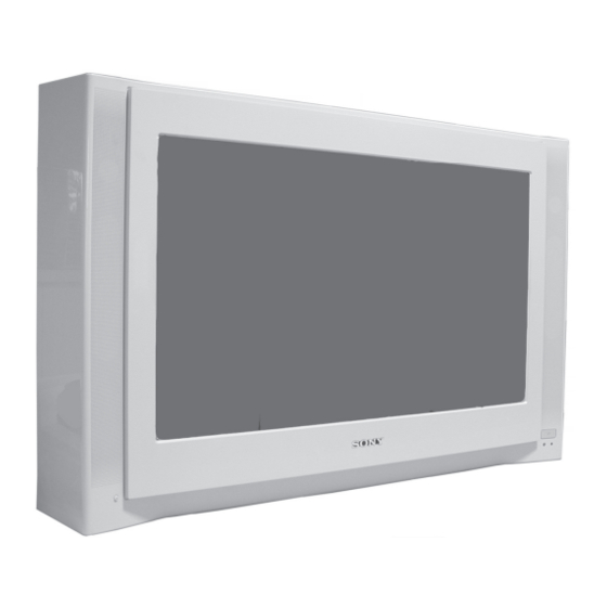
SERVICE MANUAL
MODEL
KV-28FX66B
KV-28FX66E
KV-28FX66U
COMMANDER
DEST
CHASSIS NO.
RM-937
FR
SCC-Q83H-A
RM-937
ESP
SCC-Q81K-A
RM-937
UK
SCC-Q84F-A
KV-28/32FX66
MODEL
KV-32FX66B
KV-32FX66E
KV-32FX66K
KV-32FX66U
- 1 -
AE-6B
CHASSIS
COMMANDER
DEST
CHASSIS NO.
RM-937
FR
SCC-Q83G-A
RM-937
ESP
SCC-Q81J-A
RM-937
OIRT
SCC-Q82E-A
RM-937
UK
SCC-Q84E-A
RM-937
Advertisement
Table of Contents

Summarization of Contents
Service Manual
AE-6B Chassis Identification
Identifies the chassis type of the service manual.
Cautionary Notes
Lead-Free Solder Precautions
Precautions for servicing boards using lead-free solder.
General TV Specifications
Model-Specific Feature Table
Table detailing features specific to different TV models.
21-Pin Connector Pinout
Rear Connector Panel Diagram
Diagram of the rear 21-pin connector pinout.
Front Connector Panel Diagram
Diagram of the front S-Video socket pin configuration.
AE-6B Self-Diagnostic Software
Error Menu Codes and Descriptions
List of error codes and their meanings displayed in the error menu.
General Information and Setup
Initial TV Setup and Auto Tuning
Instructions for initial TV setup, including language selection and auto-tuning.
Menu System Navigation Guide
Comprehensive guide to the TV's on-screen menu system and controls.
Teletext Service Operation
Detailed explanation of Teletext functions and operation.
NexTView Program Guide
Information on using the NexTView electronic program guide.
Remote Control VCR/DVD Setup
Guide to setting up the remote for VCR/DVD control.
Television Specifications
TV Troubleshooting Guide
Solutions for common picture and sound problems encountered with the TV.
Disassembly Procedures
Rear Cover Removal Steps
Steps to remove the rear cover of the TV for access.
Speaker Connector Disconnection
How to disconnect speaker connectors during disassembly.
Chassis Removal and Refitting
Detailed procedure for chassis removal and reinstallation.
Service Position for Access
How to position the TV chassis for service access.
G Board Removal Steps
Steps to remove the G Board from the chassis.
D2 Board Removal Steps
Steps to remove the D2 Board from the chassis.
D Board Removal Steps
Steps to remove the D Board from the chassis.
Side Control Module Removal
How to remove the side control module.
H2 Board Removal Steps
Steps to remove the H2 Board from the chassis.
M2 Board Removal Steps
Steps to remove the M2 Board from the chassis.
M2 Board Service Connector
Information on the service connector for the M2 Board.
Picture Tube Removal Procedure
Detailed procedure for removing the picture tube, including safety warnings.
Main Bracket Bottom Plate Service
Removing Main Bracket Plates
Procedure for removing main bracket bottom plates for servicing.
Refitting Main Bracket Plates
Guidelines for correctly refitting main bracket bottom plates after service.
Set-Up Adjustments Overview
Beam Landing Adjustment
Detailed steps for adjusting beam landing, including preparation and landing procedures.
Picture Adjustments
Convergence Adjustment Procedure
Procedures for screen center convergence and static convergence adjustments.
Focus and White Balance
Focus Adjustment Procedure
Steps to adjust the focus control for optimal screen focus.
Screen (G2) and White Balance Adjustment
Adjustments for G2 control and white balance settings in service mode.
Circuit Adjustments Overview
Electrical Adjustments Procedure
Procedures for performing electrical adjustments using the remote commander in service mode.
Picture and Contrast Adjustments
Sub-Brightness Adjustment
Adjusting sub-brightness for optimal signal level difference.
Sub-Contrast Adjustment
Adjusting sub-contrast for a specific voltage output.
Sub-Colour Adjustment
Adjusting sub-colour for equal levels of colour bars.
Deflection and Test Mode
Deflection System Adjustments
Adjusting various deflection parameters for optimal image display.
Test Mode 2 Operations
Accessing and utilizing Test Mode 2 for specific functions and adjustments.
Exploded Views - Chassis
Chassis Exploded View
Exploded view of the TV chassis with numbered parts and part numbers.
Exploded Views - Picture Tube
Picture Tube Exploded View
Exploded view of the picture tube assembly and associated parts.
Electrical Parts List Index
Major Board Parts Lists
Index to parts lists for major circuit boards including D, G, A, D2, C, M2, L, VM, F4, H1, H2.
Miscellaneous Parts List
List of miscellaneous parts not specific to boards.
Accessories and Packaging
List of accessories and packaging materials.
Remote Commander Parts List
Parts information for the remote commander.


Need help?
Do you have a question about the KV-32FX66B and is the answer not in the manual?
Questions and answers