Table of Contents
Advertisement
Quick Links
Download this manual
See also:
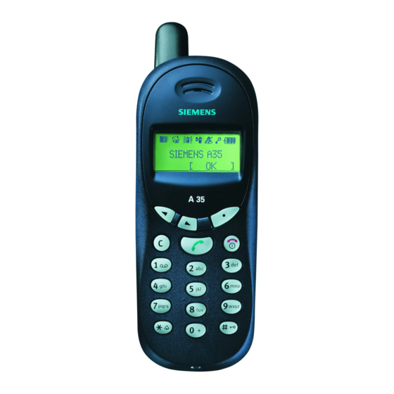
User Manual
Advertisement
Table of Contents

Related Manuals for Siemens A36


Summarization of Contents
List of Available Level 2.5e Parts
Detailed Parts Identification
Detailed list of level 2.5e parts with ID, type, function, rep-code, and order number.
Setup Requirements
Required Equipment for Level 2.5e
Lists necessary hardware equipment for level 2.5e repairs and testing.
Required Software for Level 2.5e
Specifies software requirements for level 2.5e operations and adjustments.
Radio Part Overview
4.1 Power Supply for RF Part
Details the 2.8V voltage regulators (N430/N431) for the RF part.
4.2 Frequency Generation
Covers the 13MHz VCXO and synthesizer circuits for frequency generation.
4.3 Antenna Switch Operation
Explains the electrical antenna switch for GSM900/1800 signal differentiation.
4.4 Receiver Signal Path
Details the GSM900/1800 receiver path from antenna to mixer.
4.5 Transmitter Signal Path
Describes the modulation and up-conversion loop of the transmitter.
Power Supply System
5.1 Overview and Voltages
Provides an overview of power supply concepts and voltage distribution.
5.2 STV-ASIC Functions
Details the functions of the STV-ASIC in power supply management.
5.2.1 Phone Power-On Sequence
Describes the sequence of operations for switching the phone on.
Battery and Charging System
6.1 Battery Specifications
Describes the NiMH battery specifications and temperature sensor.
6.2 Charging Concept
Explains the normal and trickle charging concepts for the battery.
Logic Part and Processor Architecture
7.1 Overview Logic
Provides an overview of the EGOLD+ and its interaction with other components.
7.2 The Flash IC
Details the functions and role of the Flash IC in the mobile phone.
7.2 Overview EGOLD+
Details the architecture and components of the EGOLD+ processor.
7.3 Overview EGAIM inside the EGOLD+
Explains the functions of the EGAIM part within the EGOLD+ processor.
MMI Functions and Interfaces
8.1 Acoustics Components
Covers electro-acoustic components: Vibra, Microphone, and Loudspeaker.
8.1.1 Vibra Motor Control
Explains the activation and control of the Vibra motor.
8.1.2 Loudspeaker as Ringer
Covers loudspeaker as ringer function and microphone connections.
8.2 Light Control
Describes the control and function of the keypad and backlight LEDs.
8.3 SIM and Display Connections
Details the SIM card and display connection interfaces and signals.
8.4 System Connectors
Lists and describes the I/O and Battery connectors.
8.4.1 I/O Connector Details
Details the pinout and function of the I/O connector.
8.4.2 Battery Connector Details
Describes the battery connector pinout and its functions.
Need help?
Do you have a question about the A36 and is the answer not in the manual?
Questions and answers