Advertisement
OPERATING & MAINTENANCE
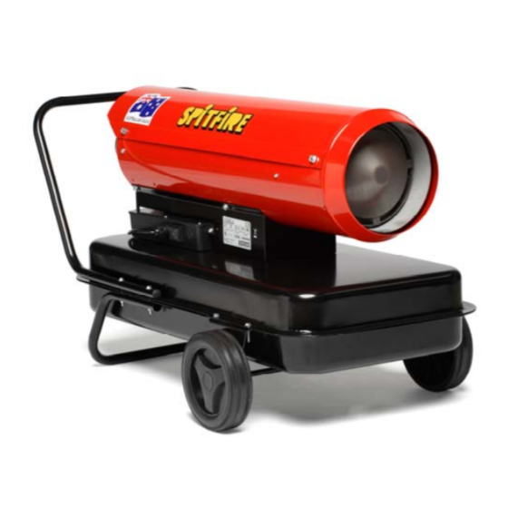
INDUSTRIAL DIRECT FIRED DIESEL/KEROSENE HEATERS
DC10 DC15 DC25 DC40 DC45
Made By:
Spitwater Australia Pty Ltd
953 Metry St. , North Albury , NSW , Australia
WARNING:
FAILURE TO FOLLOW OPERATING, SAFETY AND MAINTENANCE
INSTRUCTIONS LISTED IN THIS MANUAL RELEASES THE MANUFACTURER
FROM ANY RESPONSIBILITY FOR ACCIDENTS OR DAMAGES TO HUMANS,
ANIMALS AND OBJECTS AND MAY RENDER ANY WARRANTY VOID
MANUAL
NOT FOR DOMESTIC USE – SPACE HEATING ONLY
Advertisement
Table of Contents

Related Manuals for Spitfire DC45


Summary of Contents for Spitfire DC45
- Page 1 OPERATING & MAINTENANCE MANUAL INDUSTRIAL DIRECT FIRED DIESEL/KEROSENE HEATERS DC10 DC15 DC25 DC40 DC45 NOT FOR DOMESTIC USE – SPACE HEATING ONLY Made By: Spitwater Australia Pty Ltd 953 Metry St. , North Albury , NSW , Australia WARNING: FAILURE TO FOLLOW OPERATING, SAFETY AND MAINTENANCE INSTRUCTIONS LISTED IN THIS MANUAL RELEASES THE MANUFACTURER FROM ANY RESPONSIBILITY FOR ACCIDENTS OR DAMAGES TO HUMANS, ANIMALS AND OBJECTS AND MAY RENDER ANY WARRANTY VOID ...
- Page 2 ...
-
Page 3: Technical Data
The SPITFIRE range of heaters should only be used in the manner and purpose for which they were intended and in accordance with the recommendations and safety precautions detailed in the following Manual and in the Operating Instructions stickers on the unit itself. All SPITFIRE heaters undergo rigorous safety and operational tests before being despatched into the marketplace however it is still imperative that prior to use, all operators have read and understood all information and instructions provided and are aware of possible hazards. ... - Page 4 IMPORTANT SAFETY INSTRUCTIONS & PRECAUTIONS This booklet contains important information for the use and safe operation of this heater. Please read and understand all warnings before you start using the unit. WARNING: When using this heater: 1. Read all instructions before using this heater. 2. Know how to start and stop the unit. Be quite familiar with the controls. 3. Follow the maintenance procedures and fault‐finding techniques outlined in the manual. 4. Do not restrict under any circumstances either the inlet or outlet end of the heater. 5. Do not operate this heater in basements or below ground. 6. Permanent ventilation to the outside atmosphere must be provided. Allow 6.5cm for every 293W input divided equally between floor and high levels. 7. Not for domestic use, space heating only. 8. The heater must not be used in close proximity to combustible material. A guard must be placed 900mm away from the heater outlet to prevent the approach of combustible materials. 9. Read carefully the instructions concerning Electricity and Fuel Supply. 10. Use only clean filtered diesel or kerosene as fuel. Do not refill the fuel tank while the heater is running. 11. Do not operate the heater with the top cover removed. 12. Allow a minimum room size as listed in the technical specifications. 13. Do not pull on the electrical cord in order to unplug the unit. 14. Do not effect temporary repairs on worn or damaged electrical cords and plugs. Have worn, cut or damaged cords and plugs replaced by an authorised service ...
-
Page 5: Electricity Supply
ELECTRICITY SUPPLY The SPITFIRE range of heaters is designed to run off 220‐240V Single‐Phase 50Hz electrical supply. The unit should be plugged into a 10A outlet. WARNING: This appliance must be earthed. Note: If the Plug needs to be replaced to suit local requirements a qualified electrician should carry out the replacement taking care to earth the unit and maintain the correct phase connection as per the wiring diagram. FUEL SUPPLY Please only use the following fuel types in the heater: ... -
Page 6: Installation (All Models)
INSTALLATION AND OPERATING INSTRUCTIONS INSTALLATION (All Models) 1. Identify your unit from the model description on the serial number label affixed to the heater. 2. Where necessary. Fit wheels on axle using the clips and cover supplied. Fit axle assembly, handle and support to the tank using the bolts, nuts and washers supplied. (See Diagram Below) 3. ... - Page 7 4. Fill the Fuel Tank using clean filtered fuel. 5. Connect Power Plug to Mains Power Outlet. ...
- Page 8 OPERATING INSTRUCTIONS 1. Turn power switch to the On (I) position. This will start the ignition cycle. 2. If the heater is in lock‐out, to restart, switch the main switch on the machine off and on again after referring to point B in the troubleshooting guide. ...
- Page 9 TO STOP (NORMAL OPERATION ) 1. Turn power switch to the Off (0) position. 2. Remove the plug from the electrical outlet. ...
- Page 10 MAINTENANCE AND FAULT FINDING PROCEDURES WARNING: ALWAYS ISOLATE UNIT FROM THE ELECTRICAL SUPPLY BEFORE ATTEMPTING ANY REPAIRS OR MAINTENANCE. General: Every 150 hours: Wash inlet filter with mild detergent and dry. Filter must be thoroughly dry before replacing and must not be oiled. Every 150 hours: Check that all air lines are tight and in good condition. Every 300 hours: Replace fuel filter. Every 600 hours: Drain the fuel tank and flush it using clean fuel. Pressure Setting: Once per season or when necessary, adjust pressure setting as per procedure below. ‐The pressure setting must be adjusted to achieve a red exit cone with NO flame exiting the heater. ‐A red exit cone will ensure odour free operation. To adjust pressure setting: 1. Start and run heater until stable operating temperature is achieved. 2. With heater running, loosen lock nut A. 3. Set correct pressure by adjusting valve B. ‐Screwing the valve clockwise will increase the fuel flow and achieve a more red exit cone. ‐If flames are exiting the heater, turn the valve anti‐clockwise to reduce fuel flow. 4.
-
Page 11: Troubleshooting Guide
TROUBLESHOOTING GUIDE FAULT CAUSE REMEDY The fan motor Electricity Supply is faulty Check the power plug is plugged in. never starts If fitted: Check Thermostat setting and connections ‐ Thermostat setting is incorrect ‐ Thermostat plug is not plugged in ‐ Thermostat / thermostat connections is loose or faulty B The fan motor Diesel flow absent or low ∙ Check that the fuel tank is full. Fill if necessary. starts but unit ∙ Check fuel filter for blockages. Clean and replace as goes into necessary. lockout ∙ Check fuel line for blockages. Clean and replace as necessary. ∙ Check air line for blockages or leaks. Tighten, clean and replace as necessary. ∙ Check air filters. Clean and replace as necessary Inlet/outlet grill or inside of heater is dirty or partially blocked ∙ Check and clean as necessary Fuel is contaminated or poor quality ∙ Drain tank and replace fuel C Heater runs but Pressure adjustment is incorrect ∙ Check and adjust and clean compressor regulating excessive valve as necessary smoke or smell (Follow procedure listed in the maintenance ...
Need help?
Do you have a question about the DC45 and is the answer not in the manual?
Questions and answers