Table of Contents
Advertisement
HDR-CX500/CX500E/CX500V/CX500VE/CX505VE
SERVICE MANUAL
Ver. 1.1 2009.12
Revision History
Revision History
Link
Link
SPECIFICATIONS
MODEL INFORMATION TABLE
SERVICE NOTE
• Precaution on Replacing the VC-575 Board
• Precaution on Replacing the CABINET (BOTTOM) ASSY
• Precaution on Replacing the MM-083 Board
The components identified by
mark 0 or dotted line with
mark 0 are critical for safety.
Replace only with part num-
ber specified.
HDR-CX500/CX500E/CX500V/CX500VE/CX505VE/
CX520/CX520E/CX520V/CX520VE_L2
9-852-714-32
/CX520/CX520E/CX520V/CX520VE
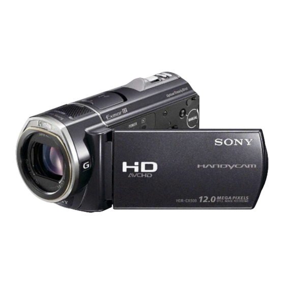
Photo: HDR-CX500
DISASSEMBLY
BLOCK DIAGRAMS
FRAME SCHEMATIC DIAGRAM
Les composants identifiés par une
marque 0 sont critiques pour la
sécurité.
Ne les remplacer que par une pièce
portant le numéro spécifié.
DIGITAL HD VIDEO CAMERA RECORDER
Sony EMCS Co.
RMT-835
LEVEL
US Model
Canadian Model
AEP Model
UK Model
North European Model
E Model
Australian Model
Hong Kong Model
Chinese Model
Korea Model
Tourist Model
Japanese Model
SCHEMATIC DIAGRAMS
PRINTED WIRING BOARDS
REPAIR PARTS LIST
Published by Tokai TEC
2
2009L0800-1
© 2009.12
Advertisement
Table of Contents

Summarization of Contents
SPECIFICATIONS
System Specifications
Details on signal format, movie recording, and photo file formats.
Recording Media and Image Device
Information on internal memory, Memory Stick PRO Duo, and image sensor details.
Lens and Optical Specifications
Focal length, zoom capabilities, filter diameter, and aperture range.
Color Temperature and Illumination
White balance settings and minimum illumination requirements.
Input/Output, LCD, and General Specs
Connectors, LCD screen size, power requirements, operating conditions.
AC Adapter and Battery Pack Details
Specifications for AC adapter (AC-L200) and NP-FH60 battery.
MODEL INFORMATION TABLE
Model and Destination Mapping
Table detailing models, destinations, color systems, and GPS function.
Abbreviation Key
Provides abbreviations for model destinations like AUS, CH, CND, HK, J, etc.
SERVICE NOTE
Power Supply During Repairs
Method to prevent unit shutdown when power is supplied to battery terminal.
VC-575 Board Replacement Precautions
Guidance on destination data, USB serial number, and data transfer for VC-575 board.
Self-Diagnosis Function and Codes
Explains the self-diagnosis display, codes, and troubleshooting table.
Shift Lens Error Troubleshooting
Procedures for addressing shift lens errors, including voltage measurements and part replacements.
GPS Receiving Check Procedure
Steps to verify GPS function and interpret GPS indicator status.
MM-083 Board Replacement Precautions
Caution regarding factory checks on MM-083 board with map data.
Cabinet Replacement Precautions
Guidelines for replacing cabinet (bottom) assemblies for various models and destinations.
DISASSEMBLY
Repair Notes and Capacitor Discharge
Safety precautions for repairs and procedure for discharging the ST-217 board's capacitor.
Identifying Parts and Disassembly Flow
Lists major internal parts and outlines the step-by-step disassembly process.
HELP Section Procedures
Detailed instructions for attaching and folding various flexible boards and components.
BLOCK DIAGRAMS
Overall Block Diagrams
Shows the interconnections between major functional blocks of the camcorder.
Power Block Diagrams
Illustrates the power distribution and regulation within the device.
SCHEMATIC DIAGRAMS
Schematic Diagram Notes and Legends
Explains symbols, component notations, and measurement conditions used in schematic diagrams.
Specific Schematic Diagram References
Lists references to detailed schematic diagrams for various boards and flexible connections.
PRINTED WIRING BOARDS
Printed Wiring Board Notes
Explains symbols and conventions used in printed wiring board diagrams.
Individual Printed Wiring Board Diagrams
Visual representations of the layout for various internal circuit boards.
REPAIR PARTS LIST
Exploded Views of Parts
Illustrates the assembly of major components with reference numbers for parts.
Electrical Parts List
Lists electrical components with part numbers, descriptions, and reference locations.
Supplied Accessories
Details included accessories such as AC adapters, cables, and manuals for different models.
Hardware List (Screws)
Comprehensive list of screws with dimensions, materials, and part numbers.


Need help?
Do you have a question about the Handycam HDR-CX520VE and is the answer not in the manual?
Questions and answers