Table of Contents
Advertisement
Advertisement
Table of Contents

Related Manuals for LG DLG2251 Series


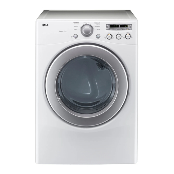
Summarization of Contents
IMPORTANT SAFETY NOTICE
General Safety Precautions
Critical safety instructions, including disconnecting power, grounding, gas leak procedures, and ESD protection.
1 SPECIFICATIONS
Dryer Accessories
Lists available optional accessories like stacking kits and pedestals for the dryer.
2 FEATURES AND BENEFITS
User Interface and Convenience Features
Highlights the easy-to-use control panel, reversible door, and SmartDiagnosis™ capability.
FlowSense™ Duct Blockage System
Details the system that monitors and alerts to clogged dryer vents for improved efficiency and safety.
3 INSTALLATION INSTRUCTIONS
Stacking Kit Installation
Step-by-step guide for safely installing the dryer on top of a washing machine using a stacking kit.
Pedestal Installation Instructions
Pedestal Installation and Leveling
Instructions for installing the pedestal accessory, including parts and leveling procedures for secure dryer placement.
Electrical Connection Options (Electric Dryer)
4-Wire Receptacle (NEMA 14-30R)
Detailed steps for connecting the dryer to a 4-wire electrical outlet.
3-Wire Receptacle (NEMA 10-30R)
Guide for connecting to a 3-wire outlet, including code considerations.
4-Wire Direct Connection
Instructions for hardwiring the dryer directly to the power supply using a 4-wire system.
Electrical Connection - Direct Wire and Cord Options
3-Wire Direct Connection
Steps for hardwiring the dryer directly to the power supply using a 3-wire system.
4-Wire Connection with Power Supply Cord
Guide for connecting to a 4-wire outlet with a power supply cord.
Electrical Connection - Optional 3-Wire
Optional 3-Wire Connection
Alternative method for 3-wire connection when frame-grounding to neutral is not permitted.
5 COMPONENT TESTING INFORMATION
Thermal and Limit Thermostat Testing
Procedures for testing thermal cut-offs, high-limit, and outlet thermostats for proper operation.
Switch and Lamp Component Tests
Instructions for testing door switches, idler switches, and lamp holders.
Component Testing - Heater, Motor, and Gas Valve
Heater, Thermistor, Motor, and Gas Valve Tests
Tests for heater, thermistor, motor, and gas valve components, including resistance checks.
Igniter and Flame Detector Testing
Procedures to test igniter and flame detector components for resistance and continuity.
Component Testing - Thermostats
Outlet Thermostat Testing (Auto/Manual Reset)
Tests for auto and manual reset outlet thermostats, including open/close resistance and continuity.
6 MOTOR DIAGRAM AND SCHEMATIC
Centrifugal Switch Operation
Explains the motor's stop and run modes, focusing on the centrifugal switch's role.
7 WIRING DIAGRAM
Electric Dryer Wiring Diagram
Visual representation of the electrical connections for the electric dryer model.
Gas Dryer Wiring Diagram
Visual representation of the electrical connections for the gas dryer model.
8 FLOW SENSOR FUNCTION
8-1 Flow Sensor Operation
Details how the FlowSense™ function detects duct blockages and alerts the user.
FlowSense™ Display Indicators
Explains the visual indicators on the control panel for duct status (Clogged vs. Normal).
9 DIAGNOSTIC TEST
Activating Diagnostic Test Mode
Steps to enter the diagnostic mode for advanced testing and troubleshooting.
Diagnostic Test Steps and Checkpoints
Outlines test sequences, display readings, and checkpoints for various dryer components.
11 DISASSEMBLY INSTRUCTIONS
Top Plate Removal
Step-by-step instructions for safely removing the dryer's top plate.
Drum Assembly and Lamp Replacement
Drum Assembly Disassembly
Steps to disassemble the tub drum assembly and adjust belts.
Changing the Drum Lamp
Procedure for replacing the interior drum light bulb and shield.
Filter, Blower Housing, and Back Cover Disassembly
Filter and Blower Housing Disassembly
Steps to remove the filter, cover grid, electrode sensor, blower housing, fan, and motor.
Back Cover Removal
Steps to remove the back cover to access internal components.
12 EXPLODED VIEW
12-1. Control Panel and Plate Assembly
Exploded diagram showing the parts of the control panel and associated plates.
Exploded View: Cabinet and Door (Electric)
12-2-1. Cabinet and Door Assembly: Electric Type
Exploded diagram illustrating the cabinet and door components for the electric dryer.
Exploded View: Cabinet and Door (Gas)
12-2-2. Cabinet and Door Assembly: Gas type
Exploded diagram illustrating the cabinet and door components for the gas dryer.
Exploded View: Drum and Motor (Electric)
12-3-1. Drum and Motor Assembly: Electric Type
Exploded diagram showing the drum and motor components for the electric dryer.
Exploded View: Drum and Motor (Gas)
12-3-2. Drum and Motor Assembly: Gas type
Exploded diagram showing the drum and motor components for the gas dryer.
Need help?
Do you have a question about the DLG2251 Series and is the answer not in the manual?
Questions and answers