Table of Contents
Advertisement
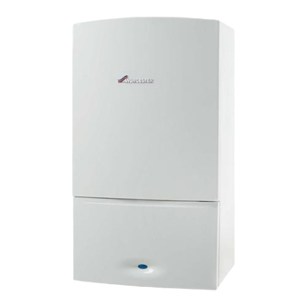
24CDi/28CDi/35CDi II
WALL MOUNTED COMBINATION BOILER FOR CENTRAL HEATING
AND MAINS FED DOMESTIC HOT WATER
INSTALLATION AND
SERVICING INSTRUCTIONS
GC NUMBER (N.G)
GC NUMBER (L.P.G.)
24CDi
28CDi
35CDi II
IMPORTANT: THESE INSTRUCTIONS APPLY IN THE UK ONLY
THESE INSTRUCTIONS ARE TO BE LEFT WITH THE USER OR AT THE GAS METER
This appliance must be installed by a competent person in accordance
with the Gas Safety (Installation and Use) Regulations 1998
RSF
24CDi
47 311 30
47 311 31
BOILER OUTPUT
Automatic Modulating Control
Domestic
Hot Water
9 - 24kW
9 - 28kW
9.5 - 35.3kW
28CDi
35CDi II
47 311 34
47 311 58
47 311 35
47 311 59
Central
Heating
9 - 24kW
9 - 24kW
10.5 - 27.5kW
Advertisement
Table of Contents

Summarization of Contents
General Information
Electrical Supply
Mains voltage, frequency, and fuse ratings.
Gas Supply
Gas type, flow rates, and pressure requirements.
Packing
How appliance and flue components are packed.
Installation
Requirements for appliance placement and ventilation.
System Notes
Flushing, inhibitor, pipework, and valve standards.
Safety Considerations
Precautions for operation, external devices, and water.
Flue
Flue system types, lengths, and components.
Controls
Descriptions of the ON/OFF switch and temperature controls.
Operation
How the boiler functions for CH and DHW modes.
Technical Data
Boiler Ratings
Nominal boiler outputs, inputs, and burner pressures.
Flue Details
Wall hole diameter and flue lengths.
Pump Head
Pump head and flow rate specifications.
Mechanical Specifications
Pipe connections, casing dimensions, and weight.
Siting The Appliance
Installation Clearances
Required space around the appliance for installation.
LPG Installation Requirements
Restrictions for LPG appliances in below ground rooms.
Installation
Fixing the Wall Mounting Plate
Steps for mounting the appliance plate.
Gas and Water Pipes
Connecting gas and water pipes to the manifold.
Install the Boiler
Attaching the boiler to the wall plate.
Commissioning
Benchmark Water Treatment
Guidelines for flushing and treating heating systems.
Summary
Overview of the commissioning process and initial settings.
Set the system pressure
Adjusting system pressure using the relief valve.
Appliance Operation
Testing burner ignition and pressure in DHW mode.
Central Heating
Testing CH operation, radiator heating, and balancing.
Domestic Hot Water and Central Heating
Testing DHW and CH combined operation.
Completion of Commissioning
Final checks and handover procedures.
Inspection And Servicing
SERVICING
Requirements and frequency for servicing.
PRE-SERVICE INSPECTION
Checks before starting service work.
Measurement of the Flue Gases
Procedure for measuring flue gas composition.
COMPONENT ACCESS
Steps to access internal components for service.
SERVICE OF COMPONENTS
Cleaning procedures for fan and main burner.
Replacement Of Parts
SAFETY
Safety precautions before replacing parts.
COMPONENT ACCESS
Steps to access components for replacement.
DRAINING THE APPLIANCE
How to drain the central heating and DHW circuits.
COMPONENT REPLACEMENT
Procedures for replacing specific parts.
Automatic Air Vent
Replacing the automatic air vent assembly.
Air Flow Pressure Switch
Replacing the air flow pressure switch.
Fan
Replacing the fan assembly.
Combustion Chamber Insulation
Replacing combustion chamber insulation pads.
Overheat Thermostat
Replacing the overheat thermostat.
Gas to Water Heat Exchanger
Replacing the gas to water heat exchanger.
Burner
Replacing the burner assembly.
Burner Injector
Replacing the burner injector.
Spark Electrode Assembly
Replacing the spark electrode assembly.
Flame Sensor
Replacing the flame sensor electrode.
Gas Valve
Replacing the gas valve and setting burner pressure.
Circulating Pump
Replacing the circulating pump.
Expansion Vessel
Replacing the expansion vessel.
Water Diverting Valve Micro Switch Assembly
Replacing the micro switch assembly on the diverter valve.
Water Diverting Valve
Replacing the water diverting valve.
Inlet Water Filter
Replacing the water filter.
Water to Water Heat Exchanger
Replacing the water to water heat exchanger.
Domestic Hot Water Flow Regulator
Replacing the DHW flow regulator.
Filling Loop
Replacing the filling loop assembly.
Control Board
Replacing the main control board.
Transformer
Replacing the transformer.
Pressure Gauge
Replacing the pressure gauge.
Operational Flow Diagrams
Central Heating Function
Flowchart for central heating operation.
Domestic Hot Water Function
Flowchart for domestic hot water operation.
Overrun Function
How the boiler operates after demand ends.
Autofrost Function
How the frost protection operates.
Fault Finding
Preliminary Checks
Initial electrical checks before fault diagnosis.
Light Situation During Fault
Mapping light indicators to fault points.
Fail Point A
Diagnosing faults related to no lights or fuse issues.
Fail Point B
Diagnosing faults related to fuse F2 or transformer.
Fail Point D
Diagnosing faults related to CH control or programmer.
Fail Point E
Diagnosing faults related to DHW operation or diverter valve.
Fail Point F
Diagnosing faults related to cold environment or pump.
Fail Point G "Primary Overheat"
Diagnosing and resolving primary overheat faults.
Fail Point H "Burner Lockout"
Diagnosing and resolving burner lockout faults.
Fail Point I "Sensor Fault"
Diagnosing and resolving sensor faults.
Fail Point J "Air Pressure Fault"
Diagnosing and resolving air pressure faults.
Fail Point K
Diagnosing faults with water temperature regulation.


Need help?
Do you have a question about the RSF and is the answer not in the manual?
Questions and answers