
Related Manuals for Atkinson Dynamics AD-27


Summarization of Contents
Introduction and Safety
Safety Precautions for Use
Critical safety instructions for installers, users, and maintenance personnel.
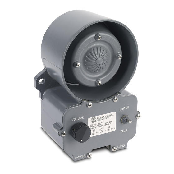
General Product Overview
Description of the intercom system, its models, and general features.
Model Specifications and Operation
Model Variants and Functions
Explains Master, Slave, and Call Button models and their operational characteristics.
Operational Cautions and Notes
Key warnings for call signals and microphone usage.
Advanced Features and Options
Microphone and Power Options
Details on headset microphones, remote power, and pre-amplifier options.
System Integration Options
Covers surge protection, foot pedals, auxiliary signals, zoned systems, and monitor switches.
Installation Guide
Unpacking and Kit Contents
Instructions for unpacking, inspection, and verifying kit contents.
Mounting Instructions
Guidelines for selecting a mounting location and physical installation.
Electrical Connection Procedures
Steps for connecting the intercom to power and audio systems.
Service and Support
Technical Assistance and Service
Information on obtaining service and technical assistance from the manufacturer.
Parts and Warranty Information
Replacement Parts List
A comprehensive list of available replacement parts for ordering.
Warranty Terms and Conditions
Details the warranty period for labor and replacement parts.
Intercom System Wiring Diagrams
Basic Two-Unit System Wiring
Diagram showing connection of two standard intercom units (Remote A & B).
Hand-Held Microphone System Wiring
Diagram illustrating system setup with a hand-held noise-cancelling microphone.
Remote Power System Wiring
Diagram showing a system with a remote unit powered by the main unit.
Master-Slave System Wiring
Diagram of a typical Master-Slave intercom setup with multiple units.
Headset/Belt Switch System Wiring
Diagram showing system connection with headset and belt switch options.
Master to Remote Speaker Wiring
Diagram for connecting a master unit to a remote speaker station.
Master to Swivel/Flush Speaker Wiring
Diagram for connecting a master to remote speakers (AD-SS/SF-25).
Multi-Master-Slave System Wiring
Diagram of a system with multiple masters and a slave using hand-held mics.
External Talk Switch System Wiring
Diagram showing intercom setup with an external momentary talk switch.
Master-Slave with External Control Wiring
Diagram illustrating a master-slave system with an external control switch.
Multi-Remote Wall/Desk Wiring
Diagram showing a master unit with multiple remote wall and desk set connections.
Auxiliary Signaling System Wiring
Diagram illustrating the connection of an auxiliary signaling device like a strobe light.
Master Monitor Switch System Wiring
Diagram showing a master unit with a monitor switch for listening to remotes.
Master/Slave Monitor Wiring
Diagram depicting a master and slave unit with monitor switch functionality.
Headset/Belt Switch System Wiring (Advanced)
Diagram of a system using headsets and belt switches for master and slave units.
Multi-Unit Headset System Wiring
Diagram showing multiple master and slave units with headset/belt switch options.
Master Selector Box System Wiring
Diagram of a system using a master selector switch box for controlling multiple remotes.
Need help?
Do you have a question about the AD-27 and is the answer not in the manual?
Questions and answers